地形系统思路来自 ProjectS中的GPU Driven
首先明确ProjectS的世界大小,目前暂定整个世界面积为 20.48km * 20.48km ,实际上可以再大很多,但考虑到资源量级以及对于世界内容的填充需要颇费心思,暂定这么大了
既然地形分了LOD,那么纹理自然也要根据LOD进行区分
LOD0的Node对应的纹理信息(高度纹理,Material Id纹理等)分辨率为128*128,覆盖区域为64m*64m即一个纹素对应0.5m,已经很可以了,再高点画质就要比原神好了
LOD1的Node纹理分辨率为128*128,但覆盖区域为128m*128m
LOD2的Node纹理分辨率为128*128,覆盖区域为256m*256m
LOD3的Node纹理分辨率为128*128,覆盖区域为512m*512m
LOD4的Node纹理分辨率为128*128,覆盖区域为1024m*1024m
LOD5的Node纹理分辨率为128*128,覆盖区域为2048m*2048m
这也就意味着我们需要对整个世界做六种不同覆盖区域的纹理,可以理解为Mipmap,不同的LOD Node采样不同覆盖区域面积的纹理,如图所示
不同颜色代表不同LOD等级,但每个LOD都是使用的128*128分辨率的高度图纹理进行渲染的,这里以原分辨率8192纹理为例,需要额外再导出4096,2048,1024,512,256的贴图,才能满足所有LOD层级的渲染需求。
需要注意的是,由于我们所有纹理都是分块流式加载的,每张纹理仅仅是128*128的,没有全分辨率的纹理,所以类似SampleLevel这种指定mip等级的API是用不了的,只能自己将相应的LOD对应纹理加载进来,由于纹理数量较多,且分辨率相同,使用Unity的TextureArray作为管理器是一个很好的选择,可以有效减少bind消耗
明确了基础的世界组成架构,接下来需要确定整个地形渲染系统的运作流程
首先是最基础的Patch,直接在houdini拉一个8x8m,分辨率为16的grid导出fbx即可
有几个注意点
记得在fbx的rop节点恢复原生比例(勾选Convert Units),不然导入到unity还得放大100倍
需要注意我们需要把mesh的UV处理一下,不然导出的mesh顶点是没有uv信息的
详情见:https://www.lfzxb.top/projects-terrian-pcg/
得益于ET的ECS代码结构形式,我们可以比较直观方便的对整个地形渲染系统进行架构
整个地形的渲染通过TerrianRenderComponent进行托管,由于我们不仅需要渲染HeightField,还有RVT,Hi-Z等内容,所以结构如下:
作为整个地形渲染的基础组件,需要提供必要的信息,我们的世界大小,四叉树的数据都由此组件维护
1
2
3
4
5
6
7
8
9
10
11
12
13
14
15
16
17
18
19
20
21
22
23
24
25
26
27
28
29
public class TerrianRenderComponent : Entity , IAwake , IDestroy , ILateUpdate { [LabelText("四叉树单个节点最大包含内容数" ) ] public int maxContentLimit = 1 ; [BoxGroup("地形" ) ] [LabelText("需要细分的距离" )] public float distanceToSplit = 300 ; #region 引用 [BoxGroup("地形" ) ] [LabelText("世界大小" )] public int worldSize = 20480 ; [BoxGroup("地形" ) ] [LabelText("世界" )] public GameObject plane; [BoxGroup("地形" ) ] [LabelText("LOD级数" )] public int lodLevelCount = 6 ; [BoxGroup("地形" ) ] [LabelText("指定四叉树大小" )] public float quadTreeSize = 4096 ; private Vector3 m_startMovePos; private Vector3 m_nextTargetPos; #endregion public QuadTree.QuadTree terrianQuadTree; public List <TerrianNode > terrianNodesnew List<TerrianNode>(); [LabelText("绘制四叉树" ) ] public bool DebugMode; #region 剔除 public Plane[] cameraFrustumPlanes = new Plane[6 ]; #endregion }
目前来说,TerrianRender的核心逻辑是在构建维护四叉树:
值得注意的是,如果没有流式加载的需求,其实是不需要标准化的四叉树的,只需要将所有需要细分的节点进行4次细分即可,完全可以将四叉树的构建和剔除放在GPU加速
而如果需要流式加载,则需要构建标准四叉树,理由如下:
随着地形渲染需求越来越高,单个Node所涵盖的资产和数据就越大,如果全都在GPU构造和剔除,在CPU阶段我们就无法得知单个Node是否需要被用到,就需要把所有资源同步至GPU,会浪费非常多的内存和显存
涉及相对复杂的数据结构和数据异步交互(例如资源加载),在GPU实现非常困难
由于我们无法保证四叉树一定是一颗完全树,所以没法用数组的形式来保存节点信息,另外我们需要动态更新四叉树,所以采用指针引用的形式进行节点存储
四叉树节点中包含的数据就是我们地形渲染中的Node:
1
2
3
4
5
6
7
8
9
10
11
12
13
14
15
16
17
18
19
20
21
22
23
24
25
26
27
28
29
30
31
32
33
34
35
36
37
38
39
40
41
42
43
44
45
46
47
48
49
50
51
52
53
54
55
56
57
58
59
public class QuadTreeNode : IReference { public int depth; public uint index; public Rect rectInfo = Rect.zero; public List <QuadTreeNode > childrennew List<QuadTreeNode>(4 ); public QuadTreeNode parent; public bool isLeafNode => children.Count == 0 ; public HashSet <QuadTreeNodeContent > containObjectnew HashSet<QuadTreeNodeContent>(); public void Clear ( foreach (var child in children) { ReferencePool.Release(child); } depth = 0 ; index = 0 ; rectInfo = Rect.zero; parent = null ; containObject.Clear(); children.Clear(); } } public class QuadTreeNodeContent : IEquatable <QuadTreeNodeContent >, IReference { public int instanceId; public Rect rectInfo = Rect.zero; public QuadTreeNode belongToQuadTreeNode; public QuadTreeNodeContent Init (int instanceId, Rect rect this .instanceId = instanceId; this .rectInfo = rect; return this ; } public void Clear ( this .instanceId = 0 ; this .rectInfo = Rect.zero; this .belongToQuadTreeNode = null ; } }
可能有些抽象,画张图解释一下
然后就是老生常谈的四叉树构造,地形节点的填入了,由于四叉树算法网上已经有很多讲解和实现,此处不再表述,可以参考:Quadtree and Collision Detection
这里只说几个注意点:
每个节点都可以存储对象,不论是否是叶子节点,可以加速查找
当一个对象不被将要被细分的四叉树节点中的四个象限中的任意一个完全包含时,将不会进行细分
当一个对象不被四叉树节点完全包含的时候,需要分配到父节点
当一个对象不被四叉树节点的四个象限中的任意一个完全包含时,需要分配到四叉树节点本身
四叉树需要有动态更新的能力
动态演示如下:
因为我们的世界是20.48km * 20.48km,且Sector为64*64m,那么如果在整个世界范围内构建四叉树的话,至少需要将四叉树的深度拉伸到9以上(即2^n >= (20480/64 = 320),n > 8 => n = 9)才能保证获取到每个Sector的LOD级数,由于四叉树深度过深,效率已经比较糟糕了
所以我们需要构建一个区域性的四叉树,尽量把四叉树深度保持在6以内,范围就是 (2^6 = 64) * 64 = 4096 ,即我们的四叉树覆盖范围为4096m*4096m,区域外的部分一律采用LOD5进行渲染
这个区域性四叉树优点如下:
较小的深度,保证查询效率
通过对比当前帧与前一帧的四叉树覆盖区域快速获得需要流式加载,卸载的节点
LOD0大小完全匹配Sector,便于后续数据准备收集工作
为后续的RVT提供数据支持
兼容任意大小的世界地形,同时可通过坐标偏移避免大世界浮点精度问题
当然对于这个区域性的四叉树,我们需要保证其中心落点一直位于64的整数倍上,不然每个Sector就对不准我们离线切分的纹理大小了
示例如下:
当玩家进行移动时,四叉树会跟随更新,如果移动连续(即不进行传送操作),则可以求出这次移动需要加载和卸载的节点
示例如下:棕色部分为待卸载部分,绿色为复用部分,蓝色为待加载部分
具体步骤为:
设当前四叉树为X
当玩家移动距离相比上一次记录累计超过LOD0(64m)阈值时触发流式
计算出需要加载的范围A,卸载的范围B,以及重合的范围C
由于我们LOD层级较多,基本上每次移动都会触发大部分节点的重建,所以直接重建整颗四叉树得到Y
将需要加载的范围A和Y做相交测试,得到覆盖的节点,以及对应的待加载资源列表a
将需要卸载的范围B和Y做相交测试,得到覆盖的节点,以及对应的待卸载资源列表b
将重合的范围C和X,Y做相交测试,得到相对的覆盖节点,对节点进行一一对比,如果节点的位置和四叉树层级(LOD等级)均相同,则认为此节点无需加载资源,否则此节点需要卸载引用资源,并重新加载新的对应资源,得到待加载的资源列表c,以及待卸载的资源d
对a,c资源列表进行加载,对b,d资源列表进行卸载
PS1:当然如果项目的资源管理模块做的比较吊的话,可以忽略上述复杂的加载卸载步骤,只需要无脑卸载上一帧残余资源,加载这一帧所有资源即可,由资源管理模块进行处理
区域性四叉树跟随移动表现如下:
当然,仅仅是这样是有问题的,因为我们是依据LOD0的阈值来重建整颗四叉树,这样会导致其余LOD等级的对应资源无法被正确加载,例如LOD1覆盖区域为128x128m,在离线切分纹理的时候每个tile是固定的,即x轴间隔0,128,256三张纹理,那么x为64的时候,是没有对应纹理的,只能继续复用x为0时的纹理。
综上,我们只有在四叉树中最高等级的LOD发生变动的时候才会移动整颗四叉树,否则以各个LOD等级贴图切分规格进行流式加载和卸载 ,示例如下:
为了最大限度利用浮点精度范围,我们把世界中心点设置在世界坐标原点处
为了和四叉树统一排列算法,世界左下角为tile0,从左到右,从下到上进行排列,就像这样:
对于地形高度渲染,每个Node至少需要有以下数据
1
2
3
4
5
6
7
8
9
10
11
12
13
14
15
16
17
18
19
20
21
22
23
24
25
26
27
28
29
30
31
32
33
34
35
36
37
38
39
40
41
42
43
44
45
46
47
48
49
50
51
52
53
54
55
56
57
58
59
60
61
62
63
64
65
66
67
68
69
70
71
72
73
74
75
76
77
78
using ET.QuadTree;using UnityEngine;namespace ET { public class TerrianNode : IReference { public long instanceId; public QuadTreeNodeContent quadTreeNodeContent; public uint lodLevel; public Vector2Int nodeIndexer; public int nodeIndex => nodeIndexer.y * nodeCount + nodeIndexer.x; public int nodeCount; public Vector2Int tileIndexer; public int tileIndex => tileIndexer.y * tileCount + tileIndexer.x; public int tileCount; public uint refHeightFieldTextureArrayIndex; public TerrianNode Init (float worldSize, QuadTree.QuadTree quadTree, QuadTreeNodeContent quadTreeNodeContent this .quadTreeNodeContent = quadTreeNodeContent; int maxLod = quadTree.maxDepthLimit - 1 ; float tilesize = 64 * Mathf.Pow(2 , maxLod); var lodSize = quadTreeNodeContent.rectInfo.size.x; int maxNodeIndex = Mathf.RoundToInt(tilesize / lodSize); lodLevel = (uint)Mathf.RoundToInt(Mathf.Log(lodSize / 64 , 2.0f )); nodeIndexer = new Vector2Int( Mathf.RoundToInt((quadTreeNodeContent.rectInfo.x + worldSize / 2 ) / lodSize) % maxNodeIndex, Mathf.RoundToInt((quadTreeNodeContent.rectInfo.y + worldSize / 2 ) / lodSize) % maxNodeIndex); tileIndexer = new Vector2Int(Mathf.FloorToInt((quadTreeNodeContent.rectInfo.x + worldSize / 2 ) / tilesize), Mathf.FloorToInt( (quadTreeNodeContent.rectInfo.y + worldSize / 2 ) / tilesize)); nodeCount = Mathf.RoundToInt(worldSize / lodSize); tileCount = Mathf.RoundToInt(worldSize / tilesize); return this ; } public void Clear ( this .quadTreeNodeContent = null ; instanceId = 0 ; refHeightFieldTextureArrayIndex = 0 ; } } }
具体的构造逻辑可见:
在将数据同步至GPU之前,我们需要先进行一次Node粒度的剔除,可以有效减少带宽和GPU剔除压力
借助四叉树的结构特性,可以实现较为高效的剔除
1 2 3 4 5 6 7 8 9 10 11 12 13 14 15 16 17 18 19 20 21 22 23 24 25 public void TraverseTree (Func<Rect, bool > trigger, Action<QuadTreeNode> traverseCallback ) TraverseTreeInternal(trigger, root, traverseCallback); } private void TraverseTreeInternal (Func<Rect, bool > trigger, QuadTreeNode quadTreeNode, Action<QuadTreeNode> traverseCallback ) if (trigger != null && !trigger.Invoke(quadTreeNode.rectInfo)) { return ; } traverseCallback?.Invoke(quadTreeNode); foreach (var child in quadTreeNode.children) { TraverseTreeInternal(trigger, child, traverseCallback); } }
碰撞检测基于相机的视锥体进行,剔除代码和debug代码如下:
1
2
3
4
5
6
7
8
9
10
11
12
13
14
15
16
17
18
19
20
21
22
23
24
25
Camera cam = Camera.main; GeometryUtility.CalculateFrustumPlanes(cam, cameraFrustumPlanes); PoolableList<QuadTreeNode> result = ReferencePool.Acquire<PoolableList<QuadTreeNode>>(); { m_quadTree.TraverseTree((x) => { Bounds cellBound = new Bounds(new Vector3(x.center.x, 0 , x.center.y), new Vector3(x.size.x, 0 , x.size.y)); return GeometryUtility.TestPlanesAABB(cameraFrustumPlanes, cellBound); }, (x) => { result.value .Add(x); }); } foreach (var quadTreeNode in result.value ){ foreach (var content in quadTreeNode.containObject) { Popcron.Gizmos.Cube(new Vector3(content.rectInfo.center.x, 0 , content.rectInfo.center.y), Quaternion.identity, new Vector3(content.rectInfo.size.x, 100 , content.rectInfo.size.y), Color.green); } } ReferencePool.Release(result);
效果如下:
我们再把目光聚焦到TerrianHeightFieldComponent上来
作为渲染地形基础骨架的组件,我们地形高度的渲染准备工作就在此组件进行
主要内容是纹理数组和一些ComputeBuffer,以及用于IndirectDraw的args
1
2
3
4
5
6
7
8
9
10
11
12
13
14
15
16
17
18
19
20
21
22
23
24
25
26
27
28
29
30
31
32
33
34
35
36
37
38
39
40
41
42
43
44
45
46
47
48
49
50
51
52
53
public class TerrianHeightFieldComponent : Entity , IAwake , IDestroy , ILateUpdate { public Dictionary <string , int > hfTextureIndexernew Dictionary<string , int >(); public Dictionary <string , TerrianResLoaderComponent.LoadState > loadStatenew Dictionary<string , TerrianResLoaderComponent.LoadState>(); #region 地形渲染 public struct HeightField_NodeInfo { public Vector2 posXZ_World; public uint lod; public uint textureArrayIndex; } public struct HeightField_PatchInfo { Vector2 belongToNodePosXZ_World; Vector2Int indexXZ_Local; uint lod; uint textureArrayIndex; } public uint[] args = new uint[5 ] { 0 , 0 , 0 , 0 , 0 }; public ComputeBuffer heightFieldNodeInfoCB; public ComputeBuffer heightFieldPatchInfoCB; public ComputeBuffer heightFieldIndirectArgCB; public Texture2DArray heightFieldTextureArray; #endregion }
组件的初始化逻辑就是数据的初始化
因为我们需要基于TextureArray进行渲染,所以需要一个纹理数组,且我们的高度图为R16深度,且分辨率为128x128,所以Unity内压缩设置为R16bit(即无压缩,一定不能对高度图进行压缩,否则会导致数据异常)
1
2
3
4
5
6
7
8
9
10
11
12
13
public class TerrianRenderComponentAwakeSystems : AwakeSystem <TerrianHeightFieldComponent >{ public override void Awake (TerrianHeightFieldComponent self ) self.heightFieldTextureArray = new Texture2DArray(128 , 128 , 512 , TextureFormat.R16, false ); self.heightFieldTextureArray.filterMode = FilterMode.Point; self.heightFieldIndirectArgCB = new ComputeBuffer(1 , self.args.Length * sizeof (uint), ComputeBufferType.IndirectArguments); self.heightFieldNodeInfoCB = new ComputeBuffer(256 , 4 * sizeof (float ), ComputeBufferType.Append); self.heightFieldPatchInfoCB = new ComputeBuffer(256 * 64 , 6 * sizeof (float ), ComputeBufferType.Append); } }
首先需要明确的一点,由于我们资源加载是异步的,所以必须保证视野变化时资源已提前加载,也就是说,我们需要额外加载视野外的资源才能保证渲染的实时性和准确性,当然这个额外加载的资源量是有限制的,一般来说:
当前视角范围及最外围相邻的资源
当前视角余角及最外围相邻的资源
看似情况复杂,其实总结下来就是:取相机xz坐标为圆心,以(当前视锥范围内距离相机最远的四叉树节点与相机的距离(取y=0)+x x x x x x
最后需要注意的是,我们并不会立即卸载那些理应卸载的节点资源,例如:
保留这部分缓存可以保证一段距离内的无感知加载,我们通过设置一个缓冲区大小和LRU策略来实现这个功能,此块实现比较业务,比较详细的思路参见:用经典的生产-消费者模型解决游戏开发中异步加载和使用问题
图示如下:
我们通过ComputeBuffer将数据同步至GPU进行计算和最终渲染
这里通过Unity URP的RenderFeature功能进行地形渲染的组织和提交,我们需要以下对象:
用于组成Node的Mesh(Patch)
用于地形渲染的Material
用于提供地形渲染所需Indirect数据的Compute Shader
1
2
3
4
5
6
7
8
9
10
11
12
13
14
15
16
17
18
19
20
21
22
public class HeightFieldRenderFeature : ScriptableRendererFeature { [System.Serializable ] public class Setting { public Mesh terrianNodeMesh; public Material terrianHeightFieldMat; public ComputeShader terrianHeightFieldCS; public RenderPassEvent passEvent = RenderPassEvent.BeforeRenderingOpaques; } public Setting setting = new Setting(); public HeightFieldRenderPass heightFieldRenderPass; public override void Create ( heightFieldRenderPass = new HeightFieldRenderPass(setting); } public override void AddRenderPasses (ScriptableRenderer renderer, ref RenderingData renderingData ) renderer.EnqueuePass(heightFieldRenderPass); } }
在配置完成之后,即可在具体的RenderPass驱动渲染,为了便于阅读代码,我省略了Dirty Update部分,从而展现完整的数据构建,提交,渲染流程
1
2
3
4
5
6
7
8
9
10
11
12
13
14
15
16
17
18
19
20
21
22
23
24
25
26
27
28
29
30
31
32
33
34
35
36
37
38
39
40
41
42
43
44
45
46
47
48
49
50
51
52
53
54
55
56
57
58
59
60
61
62
63
public override void Execute (ScriptableRenderContext context, ref RenderingData renderingData ) CommandBuffer cmd = CommandBufferPool.Get("ProjectS_RenderHeightField" ); Scene scene = Game.Scene.GetComponent<ClientSceneManagerComponent>().GetCurrentSingleGameScene(); if (scene == null ) { return ; } Init(); TerrianRenderComponent terrianRenderComponent = scene.GetComponent<Terrian>().GetComponent<TerrianRenderComponent>(); TerrianHeightFieldComponent terrianHeightFieldComponent = terrianRenderComponent.GetComponent<TerrianHeightFieldComponent>(); using (var listInstance = ReferencePool.Acquire<PoolableList<TerrianHeightFieldComponent.HeightField_NodeInfo>>()) { cmd.SetBufferCounterValue(terrianHeightFieldComponent.heightFieldNodeInfoCB, 0 ); foreach (var terrianNode in terrianRenderComponent.terrianNodes) { if (terrianHeightFieldComponent.hfTextureIndexer.TryGetValue( TerrianResLoaderComponentSystem.GetHeightFieldTextureAssetPath(terrianNode), out var index)) { terrianNode.refHeightFieldTextureArrayIndex = (uint)index; } listInstance.value .Add(new TerrianHeightFieldComponent.HeightField_NodeInfo() { lod = terrianNode.lodLevel, posXZ_World = terrianNode.quadTreeNodeContent.rectInfo.position, textureArrayIndex = terrianNode.refHeightFieldTextureArrayIndex }); } cmd.SetBufferData(terrianHeightFieldComponent.heightFieldNodeInfoCB, listInstance.value ); cmd.SetBufferCounterValue(terrianHeightFieldComponent.heightFieldPatchInfoCB, 0 ); cmd.SetComputeBufferParam(this .m_setting.terrianHeightFieldCS, m_buildPatchKernelIndex, HeightFieldNodeInfoBuffer, terrianHeightFieldComponent.heightFieldNodeInfoCB); cmd.SetComputeBufferParam(this .m_setting.terrianHeightFieldCS, m_buildPatchKernelIndex, HeightFieldPatchInfoBuffer, terrianHeightFieldComponent.heightFieldPatchInfoCB); Matrix4x4 v = terrianRenderComponent.camera.worldToCameraMatrix; Matrix4x4 p = terrianRenderComponent.camera.projectionMatrix; Matrix4x4 vp = p * v; cmd.SetComputeMatrixParam(this .m_setting.terrianHeightFieldCS, VPMatrix, vp); cmd.DispatchCompute(m_setting.terrianHeightFieldCS, m_buildPatchKernelIndex, listInstance.value .Count, 1 , 1 ); cmd.CopyCounterValue(terrianHeightFieldComponent.heightFieldPatchInfoCB, terrianHeightFieldComponent.heightFieldIndirectArgCB, sizeof (uint)); uint[] indirtCount = new uint[5 ]; terrianHeightFieldComponent.heightFieldIndirectArgCB.GetData(indirtCount); } cmd.DrawMeshInstancedIndirect(m_setting.terrianNodeMesh, 0 , m_setting.terrianHeightFieldMat, 0 , terrianHeightFieldComponent.heightFieldIndirectArgCB); context.ExecuteCommandBuffer(cmd); CommandBufferPool.Release(cmd); }
Node的来源是四叉树,为了获取更高的网格精度和渲染性能,我们的mesh大小只有8x8,但Node最小LOD都有64,所以需要将Node打散成Patch,然后进行剔除和渲染
为了避免CPU和GPU同步数据,我们让整个过程Indirect,即在GPU进行,通过Compute Shader实现
此外,为了最大限度利用GPU的并行性,我们以patch/64数量而非node数量作为dispatch目标数(因为我们numthreads为8x8)
因为基于NodeCount来处理,在最低级的LOD6上,每个Thread要写入2^6^2 = 32^2个值,而基于patch,可以让每个线程只写入1个数值即可
Node Count作为Thread count,Thread数量少,单个Thread写入数据多
Patch Count作为Thread count,Thread数量多,单个Thread写入数据少
1 cmd.DispatchCompute(m_setting.terrianHeightFieldCS, m_buildPatchKernelIndex,listInstance.value .Count, 1 , 1 );
构建patch的compute shader如下
1
2
3
4
5
6
7
8
9
10
11
12
13
14
15
16
17
18
19
20
21
22
23
24
25
26
27
28
29
30
31
32
33
34
35
36
37
38
39
40
41
42
43
44
45
46
47
48
49
50
#pragma kernel BuildPatch #define NUMTHREAD_X 8 #define NUMTHREAD_Y 8 #include "./TerrianCore.hlsl" #include "../Common/MathUtil.hlsl" RWStructuredBuffer<HeightField_NodeInfo> heightField_NodeInfoBuffer; AppendStructuredBuffer<HeightField_PatchInfo> heightField_PatchInfoBuffer; float4 frustumPlanes[6 ]; [numthreads(NUMTHREAD_X,NUMTHREAD_Y,1 )] void BuildPatch(uint3 id : SV_DispatchThreadID, uint3 groupId:SV_GroupID, uint3 groupThreadId:SV_GroupThreadID){ const HeightField_NodeInfo height_field_node_info = heightField_NodeInfoBuffer[groupId.x]; HeightField_PatchInfo height_field_patch_info; height_field_patch_info.belongToNodePosXZ_World = height_field_node_info.posXZ_World; height_field_patch_info.indexXZ_Local = uint2(groupThreadId.x, groupThreadId.y); height_field_patch_info.lod = height_field_node_info.lod; height_field_patch_info.textureArrayIndex = height_field_node_info.textureArrayIndex; float pacth_size = 8 * pow (2 , height_field_patch_info.lod); float node_size = 8 * pacth_size; const float2 localXZ_NS = ((height_field_patch_info.indexXZ_Local - 4 + 0.5 ) * pacth_size); float2 posXZ_WS = localXZ_NS + node_size / 2 + height_field_patch_info.belongToNodePosXZ_World; float half_xz = pacth_size / 2 ; float3 boundMax = float3(posXZ_WS.x + half_xz, 0 , posXZ_WS.y + half_xz); float3 boundMin = float3(posXZ_WS.x - half_xz, 0 , posXZ_WS.y - half_xz); if (FrustumCullBound(boundMin, boundMax, frustumPlanes)) { heightField_PatchInfoBuffer.Append(height_field_patch_info); } }
其中的数据结构需要同我们CPU端一致
1
2
3
4
5
6
7
8
9
10
11
12
13
14
15
16
17
18
19
struct HeightField_NodeInfo { float2 posXZ_World; uint lod; uint textureArrayIndex; }; struct HeightField_PatchInfo { float2 belongToNodePosXZ_World; int2 indexXZ_Local; uint lod; uint textureArrayIndex; };
我们可以看到FrustumCullBound函数对地形tile进行了剔除操作,思路来自:https://github.com/lijundacom/LeoGPUDriven
可以简单概括为:
计算出包围盒8个点中距离平面最近的点P n e a r P_{near} P n e a r P f a r P_{far} P f a r
如果P n e a r P_{near} P n e a r
如果P n e a r P_{near} P n e a r P f a r P_{far} P f a r
如果P n e a r P_{near} P n e a r P f a r P_{far} P f a r
计算P n e a r P_{near} P n e a r P f a r P_{far} P f a r
首先计算P m a x P_{max} P m a x P m i n P_{min} P m i n
P m a x = m a x ( P 0 , P 1 , P 2 , P 3 , P 4 , P 5 , P 6 , P 7 ) P_{max} = max(P_0,P_1,P_2,P_3,P_4,P_5,P_6,P_7) P m a x = m a x ( P 0 , P 1 , P 2 , P 3 , P 4 , P 5 , P 6 , P 7 )
P m i n = m i n ( P 0 , P 1 , P 2 , P 3 , P 4 , P 5 , P 6 , P 7 ) P_{min} = min(P_0,P_1,P_2,P_3,P_4,P_5,P_6,P_7) P m i n = m i n ( P 0 , P 1 , P 2 , P 3 , P 4 , P 5 , P 6 , P 7 )
然后
P n e a r = P m i n P_{near} = P_{min} P n e a r = P m i n
P f a r = P m a x P_{far} = P_{max} P f a r = P m a x
最后
$if(N.x > 0) P_{near}.x = P_{max}.x; $
$if(N.y > 0) P_{near}.y = P_{max}.y; $
i f ( N . z > 0 ) P n e a r . z = P m a x . z ; if(N.z > 0) P_{near}.z = P_{max}.z; i f ( N . z > 0 ) P n e a r . z = P m a x . z ;
$if(N.x > 0) P_{far}.x = P_{min}.x; $
i f ( N . y > 0 ) P f a r . y = P m i n . y ; if(N.y > 0) P_{far}.y = P_{min}.y; i f ( N . y > 0 ) P f a r . y = P m i n . y ;
i f ( N . z > 0 ) P f a r . z = P m i n . z ; if(N.z > 0) P_{far}.z = P_{min}.z; i f ( N . z > 0 ) P f a r . z = P m i n . z ;
因为我们通过GPU Instance绘制mesh,所以需要自己在vs构建uv对高度图采样,在具体公式如下
(需要注意的是,Shader中为了统一坐标系,统一转换到rect中心进行矩阵计算)
1
2
3
4
5
6
7
8
9
10
11
12
13
14
15
16
17
18
19
20
21
22
23
24
25
26
27
28
29
30
31
32
33
34
35
36
37
38
39
40
41
42
43
44
45
46
47
48
49
50
51
52
53
54
55
56
57
58
59
60
61
62
63
64
65
66
67
68
69
70
71
72
73
74
75
76
77
78
79
80
81
82
83
84
85
86
87
88
89
90
91
92
93
94
95
96
97
98
99
100
101
102
103
104
105
106
107
108
109
110
111
112
113
114
115
116
117
118
119
120
Shader "ProjectS/TerrianHeightField" { Properties { _MainTex ("颜色贴图", 2D) = "white" {} [Main(Debug, _DEBUG, on)] _debug ("调试模式", float) = 0 [SubToggle(Debug, _USE_LOCAL_UV)] _use_Local_UV("使用自身UV采样颜色", float) = 0 [SubToggle(Debug, _SHOW_UV)] _show_UV("显示UV", float) = 0 } SubShader { Tags { "RenderType" = "Opaque" "RenderPipeline" = "UniversalRenderPipeline" } Pass { Name "HeightField RenderPass" Cull Off HLSLPROGRAM #pragma enable_d3d11_debug_symbols #pragma vertex vert #pragma fragment frag #include "./TerrianCore.hlsl" #include "Packages/com.unity.render-pipelines.universal/ShaderLibrary/Core.hlsl" #pragma multi_compile_local _ _DEBUG #pragma multi_compile_local _ _USE_LOCAL_UV #pragma multi_compile_local _ _SHOW_UV TEXTURE2D_ARRAY(_heightFieldTexture2DArray); SAMPLER(sampler_heightFieldTexture2DArray); TEXTURE2D(_MainTex); SAMPLER(sampler_MainTex); CBUFFER_START(UnityPerDraw) CBUFFER_END struct Attributes { float4 positionOS : POSITION; float2 texcoord : TEXCOORD0; uint instanceId : SV_InstanceID; }; struct Varyings { float4 vertex : SV_POSITION; float2 texcoord : TEXCOORD0; }; StructuredBuffer<HeightField_PatchInfo> heightField_PatchInfoBuffer; Varyings vert(Attributes input) { Varyings output; const HeightField_PatchInfo item = heightField_PatchInfoBuffer[input.instanceId]; float4 positionOS = input.positionOS; uint scale = pow (2 , item.lod); uint nodeSize = scale * 64 ; uint patchSize = nodeSize / 8 ; positionOS.xz *= scale; const float2 localXZ_NodeSpace = positionOS.xz + ((item.indexXZ_Local - 4 + 0.5 ) * patchSize); positionOS.xz = localXZ_NodeSpace + nodeSize / 2 + item.belongToNodePosXZ_World; float2 heightFieldUV = (input.positionOS.xz * scale + (patchSize / 2 ) + (item.indexXZ_Local * patchSize)) / ((nodeSize)); float4 hfColor = SAMPLE_TEXTURE2D_ARRAY_LOD(_heightFieldTexture2DArray, sampler_heightFieldTexture2DArray, heightFieldUV, item.textureArrayIndex, 0 ); positionOS.y = hfColor.r * 117.9315 f - 18.2877 f; output.vertex = TransformObjectToHClip(positionOS.xyz); #if _DEBUG && _USE_LOCAL_UV output.texcoord = input.texcoord; #else output.texcoord = heightFieldUV; #endif return output; } float4 frag(Varyings input) : SV_Target { #if _DEBUG && _SHOW_UV return float4(input.texcoord.x, input.texcoord.y,0 ,1 ); #else return SAMPLE_TEXTURE2D(_MainTex, sampler_MainTex, input.texcoord); #endif } ENDHLSL } } CustomEditor "LWGUI.LWGUI" }
结果如下(为了方便排查问题,我已经将patch剔除去掉了)
emm,问题似乎有点多,我们一个个解决
首先猜测是UV溢出导致采样到uv = 0的纹素,通过对比发现确实如此
为了使问题更加明显,我特意畸化了一个纹理的uv = 1的边缘处:
我们输出UV看下:
看起来完全没有问题,考虑过需要手动计算UV偏移矫正(参考文末的UV坐标相关文章),但发现UV=0的地方会溢出。。。
没办法了,截帧看下:
uv边界难以捉摸,vs中uv = 1的地方默认是截至0.99998,而我们手动计算出的uv是会=1的,所以就溢出到了uv=0的地方
到头来是因为我们算的太对,违背了驱动规则,其底层原理应该和 texture-gathers-and-coordinate-precision 意思差不多(但也仅仅是意思差不多,其实不是一回事,文章里是双线性插值时主动处理临界值,而本文是不带滤波的UV溢出和驱动层舍入规则冲突),驱动层会对UV进行8位舍入
解决方式也很简单,将Texture2DArray的wrapMode设置为Clamp即可
通过下面这张图我们可以看到有些边缘是接不上的
在高度变化剧烈的区域更为明显
这是纯warframe视图
而且似乎。。。都是中间少了一个grid的信息,可能还不够明显,我们将纹理导入Houdini直接看结果
左边是原始渲染结果,右边是拼合结果,可以看出就是少了一条grid的信息导致的
找到问题根源,解决方案就很简单了,我们在导出高度图的时候额外导出1一个体素大小即可,这应该是Houdini的heightField体素计算的底层规则,会预留一些体素大小来进行拼接
1 2 output_node.parm("tile_overlapx" ).set ("1" ) output_node.parm("tile_overlapy" ).set ("1" )
重新从Houdini导出高度图,然后导入Unity,问题解决
然后地形过于尖锐是因为我一开始开启了BC4压缩优化,而BC4是有损压缩,导致高度图数据丢失,将压缩格式改回R16即可解决,当时还去RenderDoc对比了下出现接缝的两个tile数值,发现从贴图采样出的数值已经不一样了,就想到这个原因
最后加上Patch的剔除
好了,到目前为止,我们的地形已经可以渲染出来了,但其实有个不容忽视的问题,那就是我们的四叉树是没有处理高度信息的
有些朋友看到这可能有些迷惑了,这不整挺好吗,没看出啥问题?但实际上我们现在相机高度为0,和没有高度信息的四叉树是对齐的,然而地形高度已经是几十米了,也就是说有相当一部分的地块理应被剔除但被渲染了
当我们尝试移动相机高度时,地块剔除问题依旧存在,从下图可以看到,原本应该被渲染的地块被剔除掉了
这是因为,我们的四叉树是构建在y高度为0上的,这样会有个很严重的问题,一旦相机高度,角度发生变化,我们就无法在不知道y轴高度的情况下进行正确的裁剪,试想一下,相机高度为100和1的时候,往同一方向看,看到的地块应当是完全不一样的,但如果我们没有y轴信息,那么就没法正确获取这个差异性,从而无法正确裁剪,上面截图中被误剔除掉的地块也是这个原因
接下来我们需要解决这个问题,进入我们的地形渲染-二阶段
到目前为止,我们的剔除分为两个阶段,CPU Node粒度的剔除,以及GPU Patch级别的剔除
我们世界是20480*20480的,以LOD为准导出每个node最低和最高信息的话
LOD0级别数据大小为 ( 20480 64 × 8 ) 2 1024 × 1024 = 6.25 M B \frac{(\frac{20480}{64}\times8)^2}{1024\times1024} = 6.25 MB 1 0 2 4 × 1 0 2 4 ( 6 4 2 0 4 8 0 × 8 ) 2 = 6 . 2 5 M B
LOD1级别数据大小为 ( 20480 128 × 8 ) 2 1024 × 1024 = 1.5625 M B \frac{(\frac{20480}{128}\times8)^2}{1024\times1024} = 1.5625 MB 1 0 2 4 × 1 0 2 4 ( 1 2 8 2 0 4 8 0 × 8 ) 2 = 1 . 5 6 2 5 M B
LOD2级别数据大小为 ( 20480 256 × 8 ) 2 1024 × 1024 = 0.390 M B \frac{(\frac{20480}{256}\times8)^2}{1024\times1024} = 0.390 MB 1 0 2 4 × 1 0 2 4 ( 2 5 6 2 0 4 8 0 × 8 ) 2 = 0 . 3 9 0 M B
LOD3级别数据大小为 ( 20480 512 × 8 ) 2 1024 × 1024 = 0.1 M B \frac{(\frac{20480}{512}\times8)^2}{1024\times1024} = 0.1 MB 1 0 2 4 × 1 0 2 4 ( 5 1 2 2 0 4 8 0 × 8 ) 2 = 0 . 1 M B
LOD4级别数据大小为 ( 20480 1024 × 8 ) 2 1024 × 1024 = 0.02 M B \frac{(\frac{20480}{1024}\times8)^2}{1024\times1024} = 0.02 MB 1 0 2 4 × 1 0 2 4 ( 1 0 2 4 2 0 4 8 0 × 8 ) 2 = 0 . 0 2 M B
LOD5级别数据大小为 ( 20480 2048 × 8 ) 2 1024 × 1024 = 0.004 M B \frac{(\frac{20480}{2048}\times8)^2}{1024\times1024} = 0.004 MB 1 0 2 4 × 1 0 2 4 ( 2 0 4 8 2 0 4 8 0 × 8 ) 2 = 0 . 0 0 4 M B
总共约8MB的数据,我们使用二进制存储,并将数据填入四叉树节点中,流送到GPU
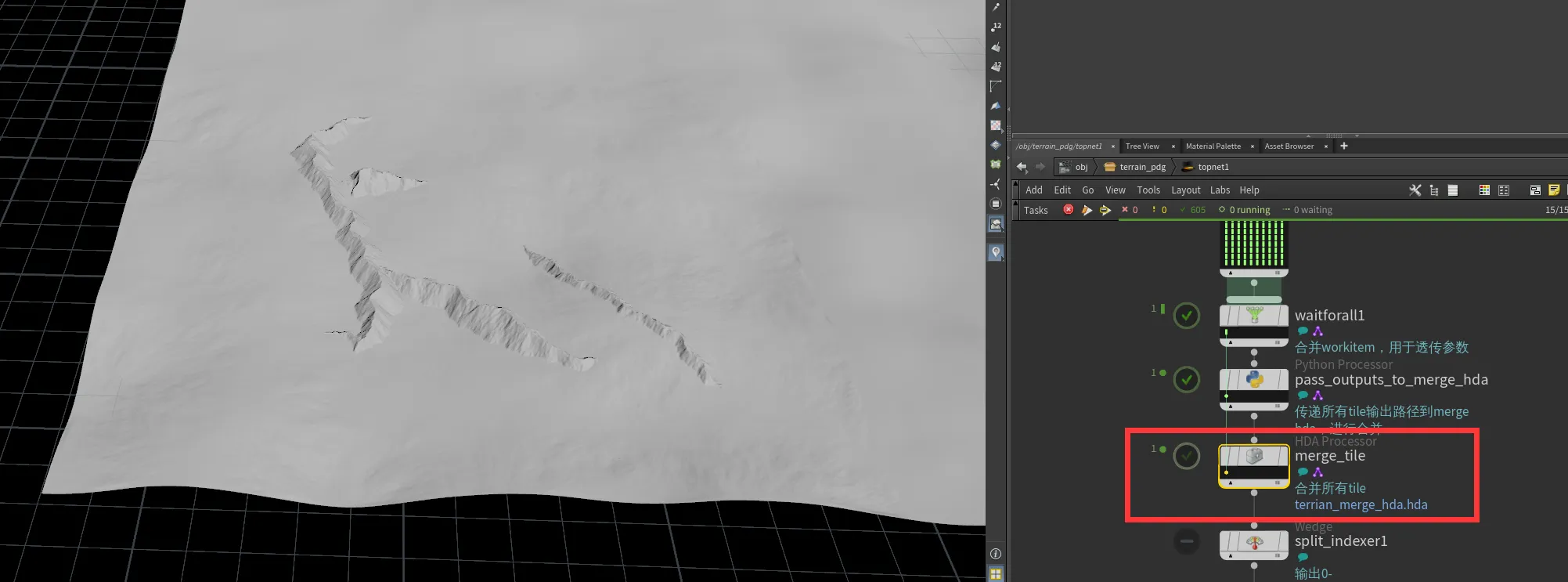
既然我们所有地形数据都来自于Houdini,那我们干脆把这些高度数据也经由Houdini导出吧,直接在PDG最后阶段加入HDA Processor指定相应HDA即可
因为CPU裁剪的粒度以Node为单位,所以我们要输出Node级别的高度信息,并且每个LOD级别都要输出
最终需要将高度数据随着TerrianNode传入GPU
1
2
3
4
5
6
7
8
9
struct HeightField_NodeInfo{ float2 posXZ_World; float2 height_Min_Max; uint lod; uint textureArrayIndex; };
最后在Compute Shader直接拿高度信息进行裁剪即可
1
2
3
4
5
6
7
float3 boundMax = float3(posXZ_WS.x + half_xz, height_field_node_info.height_Min_Max.y, posXZ_WS.y + half_xz); float3 boundMin = float3(posXZ_WS.x - half_xz, height_field_node_info.height_Min_Max.x, posXZ_WS.y - half_xz); if (FrustumCullBound(boundMin, boundMax, frustumPlanes)){ heightField_PatchInfoBuffer.Append(height_field_patch_info); }
效果:
可以看到基本上达到了较为精准的剔除,之所以镜头下方多出了一点,是因为我们采用保守剔除的方式,因为我们只记录的每个tile的最高和最低值,没法精确到每个patch的高度
其实如果是第一人称或者第三人称过肩视角,地形还有很多需要处理的事情,例如hiz遮挡剔除,不同lod之间的接缝修复,back face剔除等,但ProjectS大多数时候为俯视角,所以就不做这些得不偿失的需求了
TextureArray用法
Quadtree and Collision Detection
uv坐标是什么?
directly-mapping-texels-to-pixels
Texture Gathers and Coordinate Precision
https://github.com/lijundacom/LeoGPUDriven