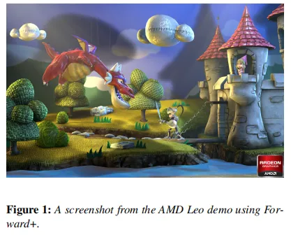
(译)Forward vs Deferred vs Forward+ Rendering with DirectX 11
在网上鲜少有能全面,具体对比Forward,Deferred,Forward+渲染管线的文章,所以抽空翻译下,分享出来
原文地址:https://www.3dgep.com/forward-plus/
In this article, I will analyze and compare three rendering algorithms:
在本文中,我将分析并比较三种渲染算法:
- Forward Rendering Forward 渲染
- Deferred Shading 延迟着色
- Forward+ (Tiled Forward Rendering)
Forward+(平铺前向渲染)
Contents
- 1 Introduction 1 介绍
- 2 Forward Rendering 2 前向渲染
- 3 Deferred Shading 3 延迟着色
- 4 Forward+ 4 Foward+
- 5 Experiment Setup and Performance Results
5 实验设置和性能结果 - 6 Future Considerations 6 未来考虑
- 7 Conclusion 7 结论
- 8 Download the Demo 下载演示
- 9 References 参考资料
Introduction 介绍
前向渲染通过对场景中的每个几何对象进行光栅化来工作。在着色过程中,会迭代场景中的光源列表,以确定如何照亮几何对象。这意味着每个几何对象都必须考虑场景中的每个光源。当然,我们可以通过丢弃被遮挡或不出现在相机视锥体中的几何对象来优化这一过程。我们可以通过丢弃不在相机视锥体内的光源进一步优化这一方式。如果光源的范围已知,那么我们可以在渲染场景几何之前对光体积执行视锥体裁剪。对象裁剪和光体积裁剪为这一方式提供了有限的优化,而在使用前向渲染管线时通常不会实践光裁剪。更常见的做法是简单地限制可以影响场景对象的光源数量。例如,一些图形引擎将对最接近的两三个光源执行每像素光照,并对接下来最接近的三四个光源执行每顶点光照。 在 OpenGL 和 DirectX 提供的传统固定功能渲染管线中,场景中任何时候活动的动态光源数量被限制在大约八个左右。即使使用现代图形硬件,前向渲染管线在出现明显帧率问题之前仅限于大约 100 个动态场景光源。
延迟着色则通过将场景中的所有对象(不带光照)光栅化到一系列 2D 图像缓冲区中,这些缓冲区存储了执行后续光照计算所需的几何信息。存储在 2D 图像缓冲区中的信息包括:
- screen space depth 屏幕空间深度
- surface normals 表面法线
- diffuse color 漫反射颜色
- specular color and specular power
镜面颜色和镜面率
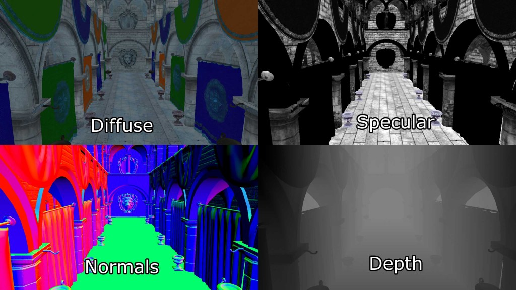
这些 2D 图像缓冲区的组合被称为几何缓冲区(或 G-Buffer)[1]。
如果需要进行后续的光照计算,其他信息也可以存储到图像缓冲区中,但每个 G-Buffer纹理在全高清(1080p)和每像素 32 位的情况下至少需要 8.29 MB 的纹理内存。
生成 G-Buffer后,几何信息可以用来在光照pass中计算光照信息。光照pass通过将每个光源渲染为场景中的几何对象来执行。每个被光源几何表示触及的像素都使用所需的光照方程进行着色。
与前向渲染相比,延迟着色方式的明显优势在于昂贵的光照计算仅针对每个受光源覆盖的像素计算一次。使用现代硬件,延迟着色方式可以处理约 2500 个动态场景光源,分辨率为全高清(1080p),在仅渲染不透明场景对象时才会出现帧率问题。
使用延迟着色的一个缺点是只有不透明物体可以被光栅化到 G-Buffer中。原因在于多个透明物体可能覆盖相同的屏幕像素,但在 G-Buffer中每个像素只能存储单个值。在光照pass中,为正在照亮的当前屏幕像素采样深度值、表面法线、漫反射和镜面颜色。由于只从每个 G-Buffer中采样单个值,透明物体无法在光照pass中受到支持。为了规避这个问题,透明几何体必须使用标准的前向渲染方式进行渲染,这限制了场景中透明几何体的数量或场景中动态光源的数量。一个只包含不透明物体的场景在出现帧速率问题之前可以处理大约 2000 个动态光源。
延迟着色的另一个缺点是在光照pass中只能模拟单个光照模型。这是因为在渲染光几何体时只能绑定单个像素着色器。对于使用超级着色器的流水线来说,使用单个像素着色器进行渲染是正常的,通常不是问题,但是如果您的渲染流水线利用各种像素着色器实现了几种不同的光照模型,那么将渲染流水线切换到使用延迟着色将会成为一个问题。
Forward+(也称为平铺前向着色)是一种渲染方式,它将前向渲染与平铺光照剔除相结合,以减少在着色过程中必须考虑的光源数量。Forward+主要包括两个阶段:
- Light culling 光照剔除
- Forward rendering 前向渲染
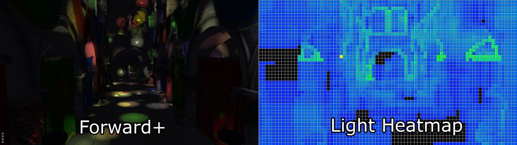
Forward+渲染方式的第一遍使用屏幕空间中的均匀网格划分灯光为每个瓦片列表。
第二遍使用标准的前向渲染传递来着色场景中的物体,但是不是遍历场景中的每个动态光源,而是使用当前像素的屏幕空间位置来查找在前一遍计算的网格中的灯光列表。光源剔除大大提高了性能,因为它大大减少了必须迭代的冗余光源数量,以正确照亮像素。不透明和透明几何体可以以类似的方式处理,而不会显著降低性能,并且使用 Forward+本地支持处理多种材质和光照模型。
由于 Forward+将标准的前向渲染管线纳入其方式中,因此 Forward+可以集成到最初使用前向渲染构建的现有图形引擎中。Forward+不使用 G-Buffer,也不受延迟着色的限制。透明和不透明几何体均可使用 Forward+进行渲染。在现代图形硬件的支持下,一个由 5,000 至 6,000 个动态光源组成的场景可以以全高清分辨率(1080p)实时渲染。
在本文的其余部分,我将描述这三种方式的实现:
- Forward Rendering Forward 渲染
- Deferred Shading 延迟着色
- Forward+ (Tiled Forward Rendering)
Forward+(平铺前向渲染)
我还将展示在各种情况下的性能统计数据,以确定在哪些条件下一种方式的表现优于其他方式。
Definitions 定义
在本文的背景下,重要的是定义一些术语,以便更容易理解文章的其余部分。如果您熟悉图形编程中使用的基本术语,可以跳过本节。
场景是指可以呈现的对象的嵌套层次结构。例如,所有可以呈现的静态对象将被分组到一个场景中。每个单独的可渲染对象在场景中使用场景节点进行引用。每个场景节点引用一个单个的可渲染对象(如网格),整个场景可以使用场景的顶级节点——根节点进行引用。场景中场景节点的连接也称为场景图。由于根节点也是一个场景节点,因此可以嵌套场景以创建具有静态和动态对象的更复杂的场景图。
一个pass是指执行渲染方式的一个步骤的单个操作。例如,不透明pass是一个遍历场景中所有对象并仅渲染不透明对象的pass。透明pass也会遍历场景中的所有对象,但仅渲染透明对象。pass也可以用于更一般的操作,比如复制 GPU 资源或dispatch compute shader。
方式是必须按特定顺序执行的几个步骤的组合,以实现渲染算法。
管线状态是指在对象渲染之前渲染管线的配置。管线状态对象封装了以下渲染状态:
- Shaders (vertex, tessellation, geometry, and pixel)
着色器(顶点、镶嵌、几何和像素) - Rasterizer state (polygon fill mode, culling mode, scissor culling, viewports)
光栅化器状态(多边形填充模式、剔除模式、剪裁剔除、视口) - Blend state 混合状态
- Depth/Stencil state 深度/模板状态
- Render target 渲染目标
DirectX 12 引入了管线状态对象,但我的管线状态定义与 DirectX 12 的定义略有不同。
Forward rendering
正向渲染是一种传统上只有两个pass的渲染方式:
- Opaque Pass 不透明pass
- Transparent Pass 透明pass
不透明pass将使场景中的所有不透明对象理想地按照从前到后(相对于摄像机)排序,以最小化过度绘制。在不透明pass期间,无需执行混合。
透明pass将使场景中的所有透明对象理想地按照从后到前(相对于摄像机)排序,以支持正确的混合。在透明pass期间,需要启用 alpha 混合,以便半透明材质能够与已经渲染到渲染目标颜色缓冲区的像素正确混合。
在正向渲染期间,所有光照都在像素着色器中执行,同时执行所有其他材质着色指令。
伪代码如下
1 | for light in lights: |
Deferred shading
延迟着色是一种渲染方式,由三个主要pass组成:
- Geometry Pass 几何pass
- Lighting Pass 灯光pass
- Transparent Pass 透明pass
第一个pass是几何pass,类似于前向渲染方式中的不透明pass,因为在这个pass中只渲染不透明物体。不同之处在于几何pass不执行任何光照计算,而只将几何和材质数据输出到在介绍中描述的 G-Buffer。
在光照pass中,代表光源的几何体积被渲染到场景中,并且使用存储在 G-Buffer中的材质信息来计算光照以用于光栅化像素。
最终pass是透明pass。该pass与正向渲染方式的透明pass相同。由于延迟着色不支持透明材质,透明物体必须在单独的pass中渲染,该pass使用标准的正向渲染方法进行光照。
1 | for mesh in meshes: |
Forward+
Forward+(也称为平铺正向渲染)是一种渲染方式,由三个主要pass组成:
- Light Culling Pass 光照剔除pass
- Opaque Pass 不透明pass
- Transparent Pass 透明pass
正如在介绍中提到的,光照剔除pass负责将场景中的动态光源排序到屏幕空间的瓦片中。一个光源索引列表用于指示哪些光源索引(来自全局光源列表)与每个屏幕瓦片重叠。在光照剔除pass中,将生成两组光源索引列表:
- Opaque light index list
不透明光索引列表 - Transparent light index list
透明光索引列表
在渲染不透明几何体时使用不透明光索引列表,在渲染透明几何体时使用透明光索引列表。
Forward+渲染方式的不透明和透明pass与标准前向渲染方式相同,但不是遍历场景中的所有动态光源,而是只需考虑当前片元屏幕空间瓦片中的光源。
Light
光指以下类型的光之一:
- Point light 点光源
- Spot light 聚光灯
- Directional light 定向光
本文中描述的所有渲染方式都支持这三种光源类型。区域光不受支持。点光源和聚光灯被模拟为从单个起源点发出,而方向光被认为是从远处无限发光,朝着同一方向到处发光。点光源和聚光灯在超出一定范围后,其强度会衰减至零。光强度的衰减称为衰减。点光源在几何上被表示为球体,聚光灯为圆锥体,方向光为全屏四边形。
让我们首先更详细地看一下标准的前向渲染方式。
前向渲染是三种光照方式中最简单、在游戏中渲染图形最常用的方式。它也是计算光照最昂贵的方式,因此不允许在场景中使用大量动态光源。
大多数使用前向渲染的图形引擎会利用各种方式来模拟场景中的许多光源。例如,光照贴图和光探针是用于预先计算场景中静态光源的光照贡献并将这些光照贡献存储在纹理中,在运行时加载的方法。不幸的是,光照贴图和光探针无法用于模拟场景中的动态光源,因为用于生成光照贴图的光源通常在运行时被丢弃。
对于这个实验,前向渲染被用作比较其他两种渲染方式的基准。前向渲染方式还被用来建立一个性能基准,可以用来比较其他渲染方式的性能。
前向渲染方式的许多功能在延迟渲染和Foward+渲染方式中得到重复利用。例如,前向渲染中使用的顶点着色器也用于延迟着色和Foward+渲染。同时,计算最终光照和材质着色的方法在所有渲染方式中得到重复利用。
在下一节中,我将描述前向渲染方式的实现。
Foward渲染实现
Vertex Shader 顶点着色器
顶点着色器适用于所有渲染方式。在这个实验中,仅支持静态几何体,没有需要不同顶点着色器的骨骼动画或地形。顶点着色器尽可能简单,同时支持像法线贴图这样的像素着色器所需的功能。
在展示顶点着色器代码之前,我将描述顶点着色器使用的数据结构。
1 | struct AppData |
AppData 结构定义了应用程序代码预期发送的数据(有关如何将数据从应用程序传递到顶点着色器的教程,请参阅我的上一篇文章,标题为《DirectX 11 入门》)。对于法线贴图,除了法线向量外,我们还需要发送切线向量,以及可选的副法线(或双切线)向量。切线和副法线向量可以由 3D 艺术家在创建模型时创建,也可以由模型导入器生成。在我的情况下,如果 3D 艺术家尚未创建切线和副切线,我依赖于 Open Asset Import Library [7] 来生成切线和副切线。
在顶点着色器中,我们还需要知道如何将应用程序发送的对象空间向量转换为像素着色器所需的视图空间。为此,我们需要将世界、视图和投影矩阵发送到顶点着色器(有关本文中使用的各种空间的回顾,请参阅我的上一篇文章,标题为坐标系)。为了存储这些矩阵,我将创建一个常量缓冲区,用于存储顶点着色器所需的每个对象变量。
1 | cbuffer PerObject : register( b0 ) |
由于我不需要单独存储世界矩阵,我在应用程序中预先计算了组合的模型、视图和组合的模型、视图和投影矩阵,并将这些矩阵一起发送到顶点着色器中的单个常量缓冲区。
顶点着色器的输出(因此也是像素着色器的输入)如下所示:
1 | struct VertexShaderOutput |
VertexShaderOutput 结构用于将转换后的顶点属性传递给像素着色器。以 VS 后缀命名的成员表示该向量是以视图空间表示的。我选择在视图空间中进行所有光照计算,而不是在世界空间中,因为在实现延迟着色和Foward+渲染方式时,使用视图空间坐标更容易。
顶点着色器非常简单和最小。它的唯一目的是将应用程序传递的对象空间向量转换为视图空间,以供像素着色器使用。
顶点着色器还必须计算由光栅化器使用的裁剪空间位置。SV_POSITION 语义被应用于顶点着色器的输出值,以指定该值用作裁剪空间位置,但此语义也可以应用于像素着色器的输入变量。当 SV_POSITION 用作像素着色器的输入语义时,该值是屏幕空间中像素的位置[8]。在延迟着色和Foward+着色器中,我将使用此语义来获取当前像素的屏幕空间位置。
1 | VertexShaderOutput VS_main( AppData IN ) |
您会注意到我正在将输入向量与矩阵进行预乘。这表明默认情况下矩阵是按列主序存储的。在 DirectX 10 之前,HLSL 中的矩阵是按行主序加载的,输入向量是由矩阵后乘的。自 DirectX 10 以来,默认情况下矩阵是按列主序加载的。您可以通过在矩阵变量声明中指定 row_major 类型修饰符来更改默认顺序。
Pixel Shader 像素着色器
像素着色器将计算用于确定单个屏幕像素最终颜色的所有光照和阴影。此像素着色器中使用的光照方程式在之前的一篇文章中描述,标题为“DirectX 11 中的纹理和光照”,如果您对光照模型不熟悉,则应该先阅读该文章,然后再继续。
像素着色器使用几个结构来完成其工作。Material 结构存储描述被着色对象的表面材质的所有信息,Light 结构包含描述放置在场景中的光源所需的所有参数。
Material 材质
Material 结构定义了描述当前被着色对象表面所需的所有属性。由于一些材质属性也可以有关联的纹理(例如,漫反射纹理、镜面反射纹理或法线纹理),我们还将使用材质来指示这些纹理是否存在于对象上。
1 | struct Material |
GlobalAmbient 术语用于描述应用于场景中所有对象的环境贡献。从方式上讲,这个变量应该是一个全局变量(而不是特定于单个对象),但由于像素着色器中一次只有一个材质,我觉得这是一个合适的放置位置。
环境光、自发光、漫反射和镜面颜色值的含义与我之前的文章《DirectX 11 中的纹理和光照》中相同,因此我不会在这里详细解释它们。
反射分量可用于指示应与漫反射颜色混合的反射颜色量。这将需要实现环境贴图,而我在这个实验中没有这样做,因此此值在此处未使用。
不透明度值用于确定物体的总不透明度。此值可用于使物体呈现为透明。此属性用于在透明pass中渲染半透明物体。如果不透明度值小于 1(1 表示完全不透明,0 表示完全透明),则该物体将被视为透明,并将在透明pass中渲染,而不是在不透明pass中。
SpecularPower 变量用于确定物体看起来有多闪亮。Specular power 在我的上一篇文章中有描述,标题为 DirectX 11 中的纹理和光照,所以我这里不会重复。
IndexOfRefraction 变量可应用于应该通过它们折射光线的物体。由于折射需要环境贴图方式,而这些方式在此实验中未实现,因此此变量将不会在此处使用。
HasTexture 变量在第 29-38 行定义,指示正在渲染的物体是否具有相关纹理。如果参数为 true,则将对应的纹理进行采样,并将 texel 与对应的材质颜色值混合。
BumpIntensity 变量用于缩放凸起贴图的高度值(不要与不需要缩放的法线贴图混淆),以软化或突出物体表面的凹凸感。在大多数情况下,模型将使用法线贴图为物体表面添加细节,而无需高细分,但也可以使用高度图来实现相同的效果。如果模型具有凸起贴图,则材质的 HasBumpTexture 属性将设置为 true,在这种情况下,模型将进行凸起贴图而不是法线贴图。
SpecularScale 变量用于缩放从镜面率纹理中读取的镜面率值。由于纹理通常将值存储为无符号归一化值,因此从纹理采样时,该值将作为浮点值读取,范围为[0…1]。镜面率为 1.0 并没有太多意义(正如我之前的文章《DirectX 11 中的纹理和光照》中所解释的那样),因此在用于最终光照计算之前,将从纹理中读取的镜面率值乘以 SpecularScale 进行缩放。
AlphaThreshold 变量可用于使用像素着色器中的“丢弃”命令丢弃不透明度低于某个值的像素。这可用于“切割”材质,其中对象不需要进行 alpha 混合,但对象应该有孔洞(例如,链环围栏)。
Padding 变量用于显式地向材质结构体添加八个字节的填充。虽然 HLSL 会隐式地向该结构体添加此填充,以确保结构体的大小是 16 字节的倍数,但显式添加填充可以清楚地表明该结构体的大小和对齐方式与其 C++对应项相同。
材质属性通过常量缓冲区传递给像素着色器。
1 | cbuffer Material : register( b2 ) |
本文描述的所有像素着色器都使用此常量缓冲区和缓冲区寄存器分配。
Textures 纹理
这些材质支持八种不同的纹理。
- Ambient 环境光
- Emissive 自发光
- Diffuse 漫反射
- Specular 镜面
- SpecularPower 反射率
- Normals 法线
- Bump 凹凸
- Opacity 不透明度
并非所有场景对象都会使用所有的纹理槽(法线和凹凸贴图是互斥的,因此它们可能会重用相同的纹理槽分配)。由 3D 艺术家决定场景中的模型将使用哪些纹理。应用程序将加载与材质关联的纹理。为每个这些材质属性声明一个纹理参数和一个关联的纹理槽分配。
1 | Texture2D AmbientTexture : register( t0 ); |
在本文中描述的每个像素着色器中,纹理槽 0-7 将被保留用于这些纹理。
Lights 灯光
Light 结构存储了定义场景中光源所需的所有信息。聚光灯、点光源和定向光源并未分开存储在不同的结构中,定义任何一种光源类型所需的所有属性都存储在单个结构中。
1 | struct Light |
位置和方向属性分别存储在世界空间(带有 WS 后缀)和视图空间(带有 VS 后缀)中。当然,位置变量仅适用于点光源和聚光灯,而方向变量仅适用于聚光灯和方向光源。我同时存储世界空间和视图空间的位置和方向向量,因为我发现在应用程序中更容易在世界空间中工作,然后在将世界空间向量转换为视图空间之前将灯光数组上传到 GPU。这样,我就不需要维护多个光源列表,而需要的额外空间仅在 GPU 上。即使有 10,000 个光源,也仅需要 1.12 MB 的 GPU 空间,所以我认为这是一个合理的牺牲。但是,减小光源结构的大小可能对 GPU 上的缓存产生积极影响,并提高渲染性能。这在本文末尾的未来考虑部分进一步讨论。
在一些光照模型中,漫反射和镜面反射的光照贡献是分开的。我选择不分开漫反射和镜面反射的颜色贡献,因为这些值不经常不同。相反,我选择将漫反射和镜面反射的光照贡献都存储在一个名为 Color 的单个变量中。
SpotlightAngle 是以度为单位表示的聚光灯锥体的半角。使用度数似乎比使用弧度更直观。当我们需要计算聚光灯和光矢量的余弦角时,聚光灯角度当然会在着色器中转换为弧度。
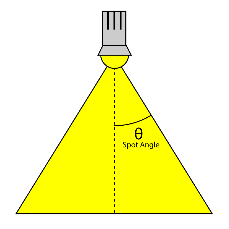
Spotlight Angle 聚光灯角度
范围变量确定光线的到达距离,并仍然为表面提供光线。虽然不完全符合物理规律(真实光源具有永远不会真正达到 0 的衰减),但需要光源具有有限范围以实现延迟着色和Foward+渲染方式。这个范围的单位是特定于场景的,但通常我尝试遵守 1 单位等于 1 米的规范。对于点光源,范围是代表光源的球体的半径,对于聚光灯,范围是代表光源的锥体的长度。定向光不使用范围,因为它们被认为是无限远,无论在哪里指向相同方向。
强度变量用于调节计算得到的光照贡献。默认情况下,该值为 1,但可以用来使一些灯光比其他灯光更亮或更微妙。
场景中的灯光可以通过 Enabled 标志进行开关控制。Enabled 标志为 false 的灯光将在着色器中被跳过。
在此演示中,灯光是可编辑的。可以通过在演示应用程序中单击灯光来选择灯光并修改其属性。要表示当前选择的灯光,Selected 标志将被设置为 true。当在场景中选择灯光时,其视觉表示将变暗(不透明度降低),以表示当前选择的状态。
Type 变量用于指示这是哪种类型的光。它可以具有以下值之一:
1 |
再次,Light 结构体明确填充了 8 字节,以匹配 C++ 中的结构布局,并使结构体明确对齐到 16 字节,这在 HLSL 中是必需的。
通过 StructuredBuffer 访问 lights 数组。大多数光照着色器实现将使用常量缓冲区来存储 lights 数组,但常量缓冲区的大小限制为 64 KB,这意味着在 GPU 上的常量内存用完之前,lights 数组将受到限制,大约只能容纳约 570 个光源。Structured buffers 存储在纹理内存中,其大小受 GPU 上可用纹理内存的限制(通常在台式机 GPU 上为 GB 级别)。大多数 GPU 上的纹理内存速度也非常快,因此将 lights 存储在结构化缓冲区中并不会对性能产生影响。事实上,在我的特定 GPU(NVIDIA GeForce GTX 680)上,当我将 lights 数组移动到结构化缓冲区时,我注意到了显著的性能改进。
1 | StructuredBuffer<Light> Lights : register( t8 ); |
Pixel Shader Continued 像素着色器
正向渲染方式的像素着色器比顶点着色器稍微复杂一些。如果您已经阅读了我之前的文章《DirectX 11 中的纹理和光照》,那么您应该已经熟悉了这个着色器的大部分实现,但我会在这里详细解释,因为它是本文中展示的所有渲染算法的基础。
Materials 材质
首先,我们需要收集材质的材质属性。如果材质具有与其各个组件相关联的纹理,那么在计算光照之前将对纹理进行采样。初始化材质属性后,将迭代场景中的所有灯光,并将光照贡献累积并与材质属性调制,以生成最终像素颜色。
1 | [earlydepthstencil] |
在函数之前的[earlydepthstencil]属性表示 GPU 应该利用提前深度和模板剔除[10]。这会导致深度/模板测试在像素着色器执行之前执行。这个属性不能用于修改像素深度值的着色器,因为它使用 SV_Depth 语义输出值。由于这个像素着色器只使用 SV_TARGET 语义输出颜色值,它可以利用提前深度/模板测试来提高性能,当像素被拒绝时。大多数 GPU 即使没有这个属性也会执行提前深度/模板测试,将这个属性添加到像素着色器并没有明显影响性能,但我还是决定保留这个属性。
由于所有的光照计算将在视图空间中执行,眼睛位置(相机的位置)始终为(0, 0, 0)。这是在视图空间中工作的一个好处;相机的眼睛位置不需要作为额外参数传递给着色器。
在第 24 行,将材质的临时副本创建,因为如果材质属性有关联的纹理,那么在着色器中将修改这些属性。由于材质属性存储在常量缓冲区中,无法直接从常量缓冲区统一变量更新材质属性,因此必须使用本地临时变量。
Diffuse 漫反射
我们将要阅读的第一个材质属性是漫反射颜色。
1 | float4 diffuse = mat.DiffuseColor; |
默认的漫反射颜色是分配给材质的 DiffuseColor 变量的漫反射颜色。如果材质还有与之关联的漫反射纹理,那么来自漫反射纹理的颜色将与材质的漫反射颜色混合。如果材质的漫反射颜色是黑色(0, 0, 0, 0),那么材质的漫反射颜色将简单地被漫反射纹理中的颜色替换。任何 hlsl 内置函数都可以用来查找颜色分量中是否有任何非零值。
Opacity 不透明度
像素的 alpha 值是接下来确定的。
1 | float alpha = diffuse.a; |
默认情况下,片元的透明度值由漫反射颜色的 alpha 分量确定。如果材质有与之关联的不透明度纹理,不透明度纹理的红色分量将用作 alpha 值,覆盖漫反射纹理中的 alpha 值。在大多数情况下,不透明度纹理仅存储从 Sample 方法返回的颜色的第一个分量中的单个pass。为了从单pass纹理中读取,我们必须从红色pass读取,而不是从 alpha pass读取。单pass纹理的 alpha pass将始终为 1,因此从不透明度图中读取 alpha pass(这很可能是单pass纹理)将无法提供我们需要的值。
Ambient and Emissive 环境和自发光
环境色和发射色的读取方式与漫反射色类似。环境色还与材质的 GlobalAmbient 变量的值相结合。
1 | float4 ambient = mat.AmbientColor; |
Specular Power 反射率
接下来计算镜面率。
1 | if ( mat.HasSpecularPowerTexture ) |
如果材质具有关联的高光强度纹理,纹理的红色分量将被采样并乘以材质的 SpecularScale 变量的值。在这种情况下,材质中的 SpecularPower 变量的值将被替换为纹理中的缩放值。
Normals 正常
如果材质具有关联的法线贴图或凹凸贴图,则将执行法线贴图以计算法线向量。如果材质未关联法线贴图或凹凸贴图纹理,则输入法线将按原样使用。
1 | // Normal mapping |
Normal Mapping 法线贴图
DoNormalMapping 函数将从 TBN(切线、双切线/法线副切线、法线)矩阵和法线贴图执行法线采样。
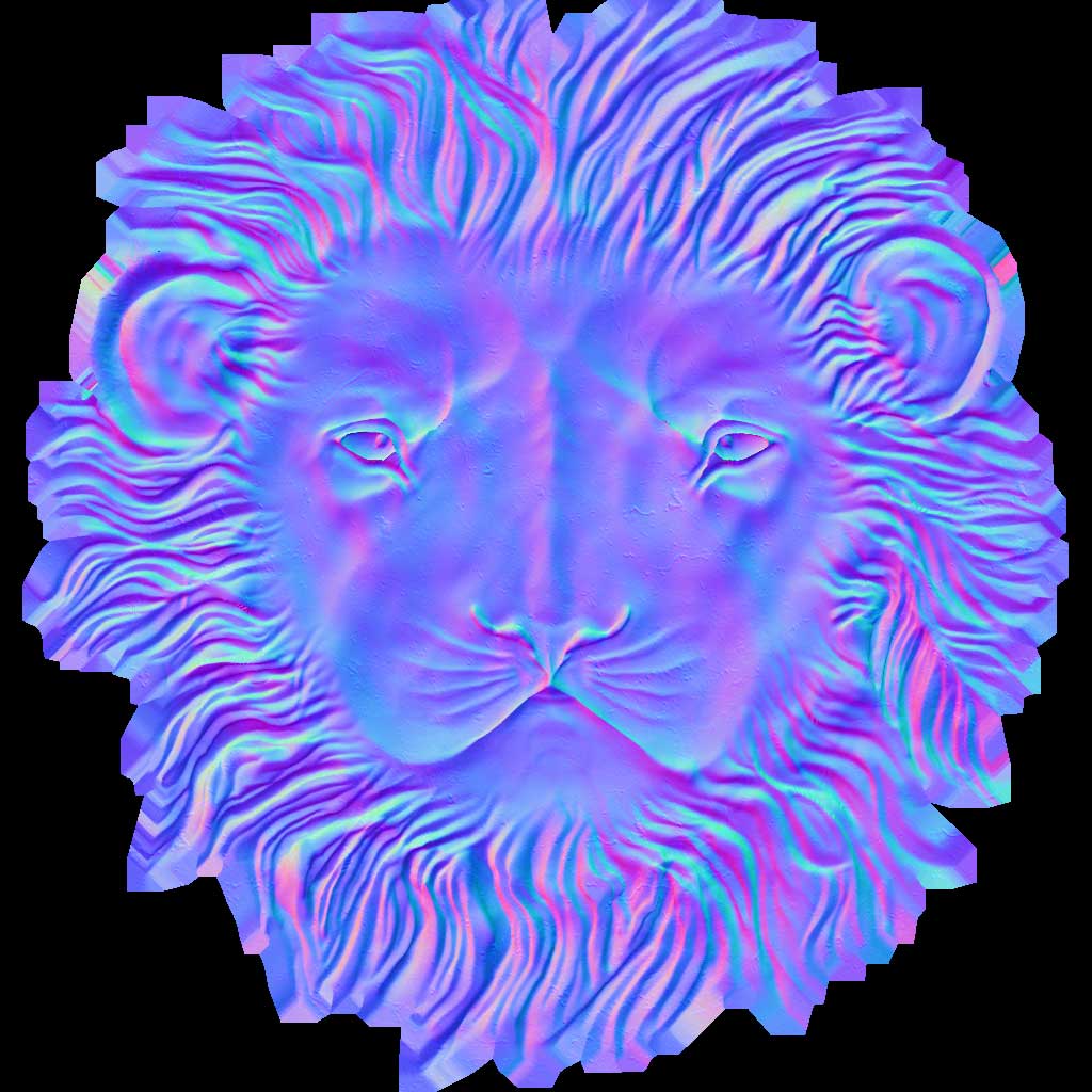
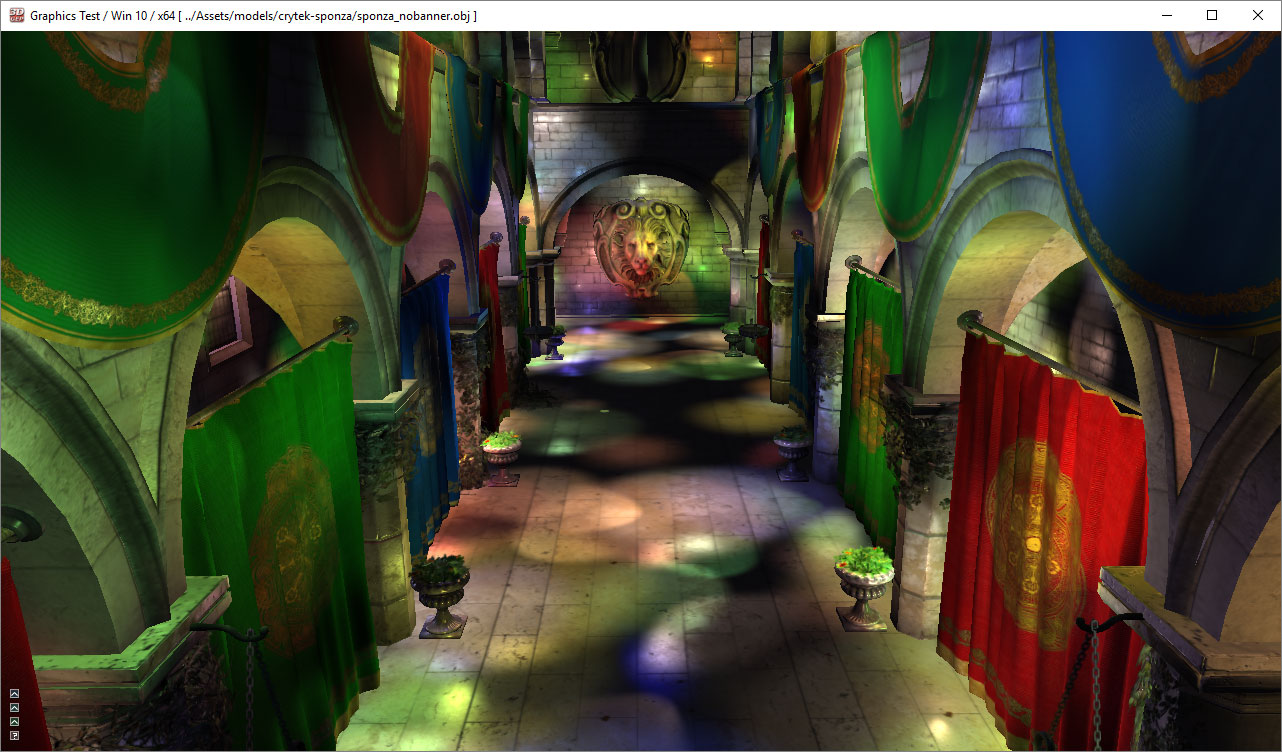
狮子头在 Crytek Sponza 场景中的一个示例法线贴图纹理。[11]
1 | float3 ExpandNormal( float3 n ) |
普通贴图非常简单,之前的一篇名为“法线贴图”的文章中对此进行了更详细的解释,所以我就不在这里详细解释了。基本上,我们只需要从法线贴图中采样法线,将法线扩展到[-1…1]范围内,并通过将其与 TBN 矩阵进行后乘来将其从切线空间转换到视图空间。
Bump Mapping 凹凸贴图
凹凸贴图的工作方式类似,不同之处在于凹凸贴图纹理中不直接存储法线,而是存储高度值,范围为[0…1]。可以通过计算高度图中 U 和 V 纹理坐标方向上的高度值梯度来生成法线。在每个方向上梯度的叉积给出了纹理空间中的法线。将结果法线与 TBN 矩阵相乘将给出视图空间中的法线。从凹凸贴图中读取的高度值可以缩放以产生更多(或更少)突出的凹凸效果。
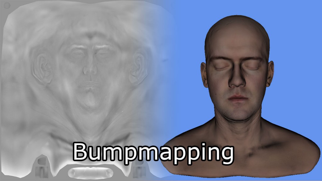
凹凸贴图纹理(左)和相应的头部模型(右)。【12】
1 | float4 DoBumpMapping( float3x3 TBN, Texture2D tex, sampler s, float2 uv, float bumpScale ) |
我不确定这个凹凸贴图算法是否 100%正确。我找不到任何资源显示如何正确地进行凹凸贴图。如果您能提出更好(和正确)的执行凹凸贴图的方法,请在下面留言。
如果材质没有关联的法线贴图或凹凸贴图,则直接使用顶点着色器输出的法线向量。
现在我们拥有计算光照所需的所有数据。
Lighting 灯光
正向渲染方式的灯光计算是在 DoLighting 函数中执行的。该函数接受以下参数:
- lights: The lights array (as a structured buffer)
灯光:灯光数组(作为结构化缓冲区) - mat: The material properties that were just computed
材质属性刚刚计算出来的 - eyePos: The position of the camera in view space (which is always (0, 0, 0))
eyePos: 相机在视图空间中的位置(始终为(0, 0, 0)) - P: The position of the point being shaded in view space
P: 在视图空间中被着色的点的位置 - N: The normal of the point being shaded in view space.
N:在视空间中着色的点的法线。
DoLighting 函数返回一个 LightingResult 结构,其中包含场景中所有灯光的漫反射和镜面光照贡献。
1 | // This lighting result is returned by the |
视图向量(V)是从眼睛位置和视图空间中阴影像素的位置计算得出的。
光缓冲区在第 439 行上进行迭代。由于我们知道禁用的灯光和不在被着色点范围内的灯光不会提供任何光照,我们可以跳过这些灯光。否则,根据灯光类型调用适当的光照函数。
各种光源类型将计算它们的漫反射和镜面反射光照贡献。由于漫反射和镜面反射光照对于每种光源类型的计算方式相同,我将定义函数来计算漫反射和镜面反射光照贡献,独立于光源类型。
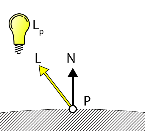
Diffuse Lighting 漫反射光照
DoDiffuse 函数非常简单,只需要知道光矢量(L)和表面法线(N)即可。
Diffuse Lighting 漫射光
1 | float4 DoDiffuse( Light light, float4 L, float4 N ) |
漫反射光照是通过计算光矢量(L)和表面法线(N)之间的点积来实现的。DoDiffuse 函数期望这两个向量都被归一化。
然后将得到的点积乘以光的颜色,以计算光的漫反射贡献。
接下来,我们将计算光的镜面贡献。
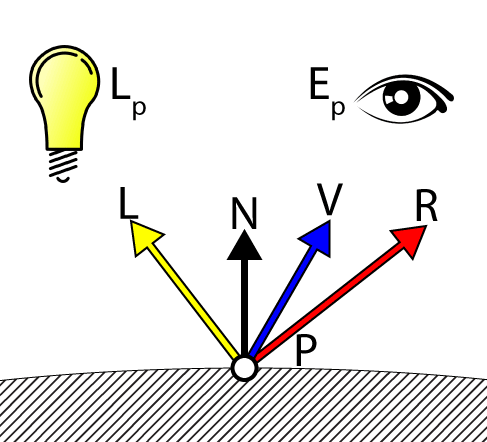
Specular Lighting 镜面光照
DoSpecular 函数用于计算光的镜面贡献。除了光矢量(L)和表面法线(N)之外,该函数还需要视图矢量(V)来计算光的镜面贡献。
Specular Lighting 镜面光照
1 | float4 DoSpecular( Light light, Material material, float4 V, float4 L, float4 N ) |
由于光矢量 L 是从被着色点指向光源的矢量,所以在计算反射矢量之前,需要对其取反,使其从光源指向被着色点。反射矢量(R)和视图矢量(V)的点积结果被提升到材质的高光率变量的值,并受光的颜色调制。重要的是要记住,范围在(0…1)的高光率值并不是一个有意义的高光率值。有关高光光照的详细解释,请参阅我之前发表的文章,标题为《DirectX 11 中的纹理和光照》。
Attenuation 衰减
衰减是光强随着光离被遮挡点的距离增加而减弱的过程。在传统的光照模型中,衰减被计算为三个衰减因子之和的倒数乘以到光源的距离(如在衰减中所解释的)。
- Constant attenuation 恒定衰减
- Linear attenuation 线性衰减
- Quadratic attenuation 二次衰减
然而,这种计算衰减的方法假设光线的衰减永远不会达到零(灯光具有无限范围)。对于延迟着色和前向加法,我们必须能够将场景中的灯光表示为具有有限范围的体积,因此我们需要使用不同的方法来计算光线的衰减。
计算光线衰减的一种可能方法是从 1.0 开始进行线性混合,当点最靠近光源时为 1.0,如果点的距离大于光源的范围,则为 0.0。然而,线性衰减看起来并不是很现实,因为实际上衰减更类似于二次函数的倒数。
我决定使用 smoothstep hlsl 内置函数,该函数返回最小值和最大值之间的平滑插值。
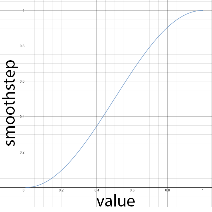
HLSL smoothstep 内置函数
1 | // Compute the attenuation based on the range of the light. |
smoothstep 函数将在距离光源的距离(d)小于光源范围的 3/4 时返回 0,在距离光源的距离大于范围时返回 1。当然,我们希望反转这种插值,所以我们只需从 1 中减去这个值,以获得我们需要的衰减。
可选地,我们可以通过上述方程中的 0.75f 的参数化来调整光线衰减的平滑度。平滑度因子为 0.0 应导致光线的强度一直保持为 1.0,直到光线的最大范围,而平滑度为 1.0 应导致光线的强度在整个光线范围内插值。
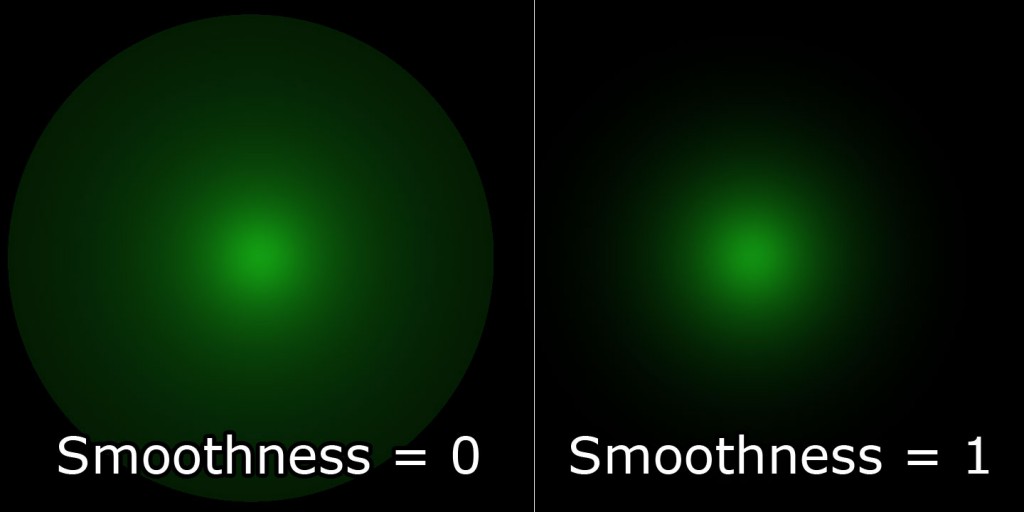
变量衰减平滑度。
现在让我们结合漫反射、镜面反射和衰减因子来计算每种光类型的光照贡献。
Point Lights 点光源
点光源结合衰减、漫反射和镜面反射值来确定光的最终贡献。
1 | LightingResult DoPointLight( Light light, Material mat, float4 V, float4 P, float4 N ) |
在第 400-401 行,漫反射和镜面反射的贡献在从函数返回之前会被衰减和光强因子缩放。
Spot Lights 聚光灯
除了衰减因子外,聚光灯还有一个锥角。在这种情况下,光的强度由光矢量(L)与聚光灯方向之间的点积来缩放。如果光矢量与聚光灯方向之间的角度小于聚光灯锥角,则该点应该被聚光灯照亮。否则,聚光灯不应该为被遮蔽的点贡献任何光线。DoSpotCone 函数将根据聚光灯锥角计算光的强度。
1 | float DoSpotCone( Light light, float4 L ) |
首先,计算聚光锥的余弦角。如果聚光灯方向与光矢量(L)的点积小于最小余弦角,则光的贡献将为 0。如果点积大于最大余弦角,则聚光的贡献将为 1。
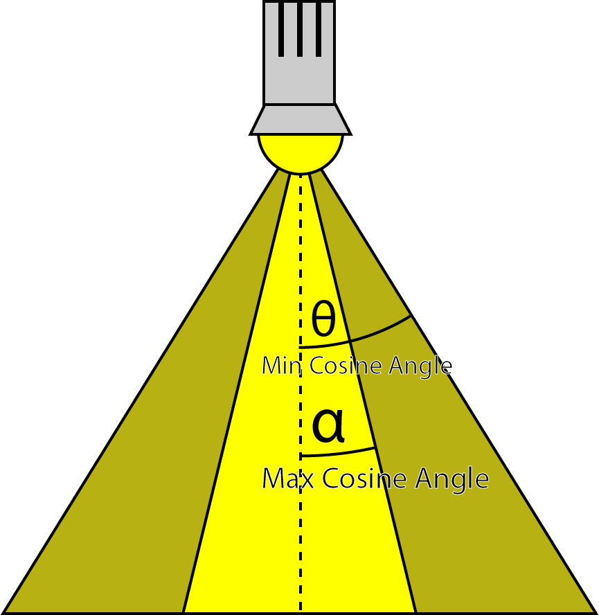
聚光灯的最小和最大余弦角。
看起来可能有些反直觉,最大余弦角比最小余弦角小,但不要忘记 0°的余弦是 1,90°的余弦是 0。
DoSpotLight 函数将计算聚光灯的贡献,类似于点光源,但增加了聚光锥角。
1 | LightingResult DoSpotLight( Light light, Material mat, float4 V, float4 P, float4 N ) |
Directional Lights 定向光
定向光是最简单的光类型,因为它们不会随着到达被着色点的距离而衰减。
1 | LightingResult DoDirectionalLight( Light light, Material mat, float4 V, float4 P, float4 N ) |
Final Shading 最终着色
现在我们有场景中所有灯光的材质属性和总和光照贡献,我们可以将它们组合起来执行最终的着色。
1 | float4 P = float4( IN.positionVS, 1 ); |
在第 113 行,使用刚刚描述的 DoLighting 函数计算光照贡献。
在第 115 行,材质的漫反射颜色受到光的漫反射贡献的调制。
如果材质的高光强度低于 1.0,则不会被考虑用于最终着色。一些艺术家会为没有高光反射的材质分配低于 1 的高光强度。在这种情况下,我们只忽略高光的贡献,将材质视为仅有漫反射(兰伯特反射)。否则,如果材质带有高光颜色纹理,将对其进行采样并与材质的高光颜色结合,然后再与光的高光贡献调制。
最终像素颜色是环境光、自发光、漫反射和高光分量的总和。像素的不透明度由像素着色器中先前确定的 alpha 值决定。
Deferred Shading 延迟渲染
延迟渲染方式包括三个pass:
- G-buffer pass
- Lighting pass
- Transparent pass
G 缓冲pass将填充介绍中描述的 G 缓冲纹理。光照pass将每个光源渲染为几何对象,并计算覆盖像素的光照。透明pass将使用标准的前向渲染方式渲染透明场景对象。
G-Buffer Pass
延迟着色方式的第一步将生成 G 缓冲纹理。我将首先描述 G 缓冲的布局。
G-Buffer Layout
G-buffer 的布局可以成为本网站上一篇完整文章的主题。我为这个演示选择的布局是基于简单和必要性的。这不是最有效的 G-buffer 布局,因为一些数据可以更好地打包到更小的缓冲区中。关于在 G-buffer 中打包属性已经有一些讨论,但我没有进行任何关于使用各种打包方法的效果的分析。
需要存储在 G-buffer 中的属性是:
- Depth/Stencil 深度/模板
- Light Accumulation 光照累加
- Diffuse 漫反射
- Specular 高光
- Normals 法线
Depth/Stencil Buffer 深度/模板缓冲区
深度/模板纹理以每像素 32 位存储,其中深度值为 24 位,作为无符号归一化值(UNORM),模板值为 8 位,作为无符号整数(UINT)。 深度缓冲区的纹理资源使用 R24G8_TYPELESS 纹理格式创建,深度/模板视图使用 D24_UNORM_S8_UINT 纹理格式创建。 在像素着色器中访问深度缓冲区时,着色器资源视图使用 R24_UNORM_X8_TYPELESS 纹理格式创建,因为模板值未使用。
深度/模板缓冲区将附加到输出合并阶段,并且不会直接在 G 缓冲像素着色器中计算。 顶点着色器的结果直接写入深度/模板缓冲区。
(需要注意的是,此处的深度模板缓冲区是由Deferred Render创建的,而非渲染流水线的深度模板缓冲区,是两份资源,称之为自定义深度缓冲区更合适,对于Unity的_CameraDepthTexture就是Unity帮我们从深度缓冲区拷贝的一个深度纹理,我们完全可以像Deferred Render这样自己绘制一份DepthTexture)
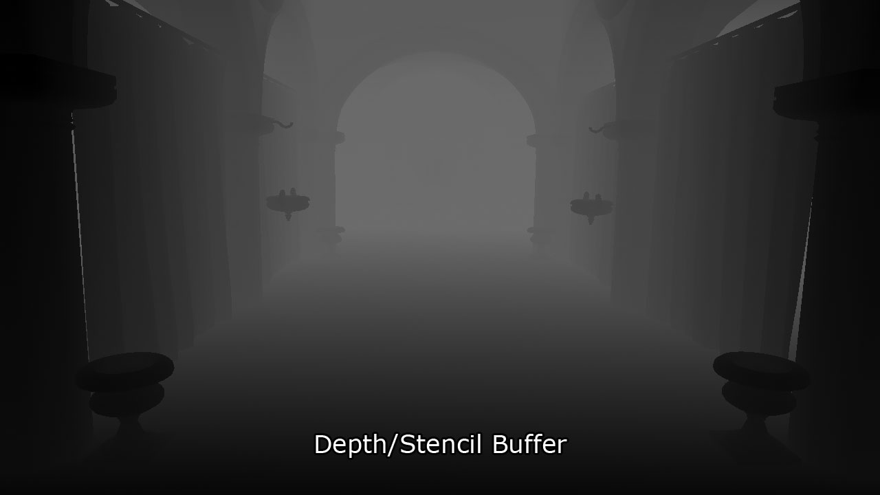
G-buffer pass中深度/模板缓冲区的输出
Light Accumulation Buffer
光积累缓冲区用于存储光照pass的最终结果。这与屏幕的后备缓冲区相同。如果您的 G 缓冲纹理与屏幕的尺寸相同,则无需为光积累缓冲区分配额外的缓冲区,可以直接使用屏幕的后备缓冲区。
光积累缓冲区存储为 32 位 4 分量无符号归一化纹理,使用 R8G8B8A8_UNORM 纹理格式作为纹理资源和着色器资源视图。
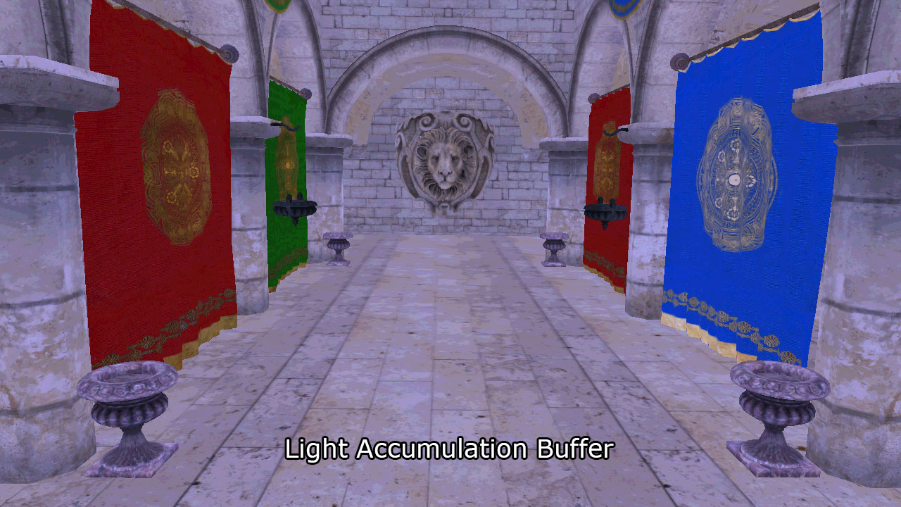
光积累缓冲区存储发射和环境项。为了使场景更加清晰可见,这幅图像已经明显变亮。
在 G 缓冲pass之后,光积累缓冲区最初仅存储光照方程中的环境和自发项。为了使其更加可见,这幅图像被明显加亮。
您可能还注意到场景中仅呈现完全不透明的对象。延迟着色不支持透明对象,因此在 G 缓冲pass中仅呈现不透明对象。
作为一种优化,您可能还希望在 G 缓冲pass中累积定向光,并在光照pass中跳过定向光。由于定向光在光照pass中呈现为全屏幕四边形,如果填充率是一个问题,那么在 G 缓冲pass中累积它们可能会节省一些着色器周期。在这个实验中,我没有利用这种优化,因为这将需要将定向光存储在一个单独的缓冲区中,这与前向和Foward+像素着色器处理光照的方式不一致。
Diffuse Buffer 漫反射Buffer
漫反射缓冲区存储为 32 位 4 分量无符号归一化(UNORM)纹理。由于延迟着色中只渲染不透明对象,因此在此缓冲区中不需要 alpha pass,在此实验中保持未使用。纹理资源和着色器资源视图均使用 R8G8B8A8_UNORM 纹理格式。
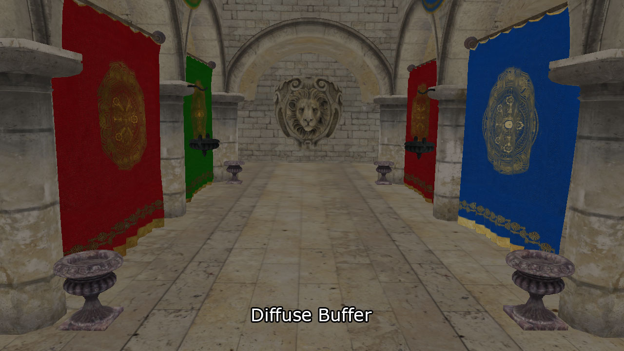
G-buffer pass后的漫反射缓冲区。
上述图像显示了 G-buffer pass后漫反射缓冲区的结果。
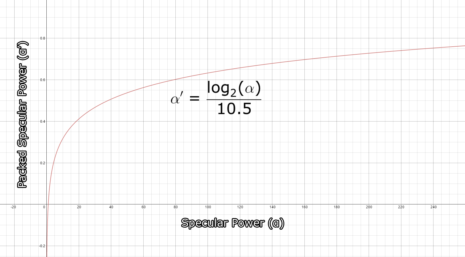
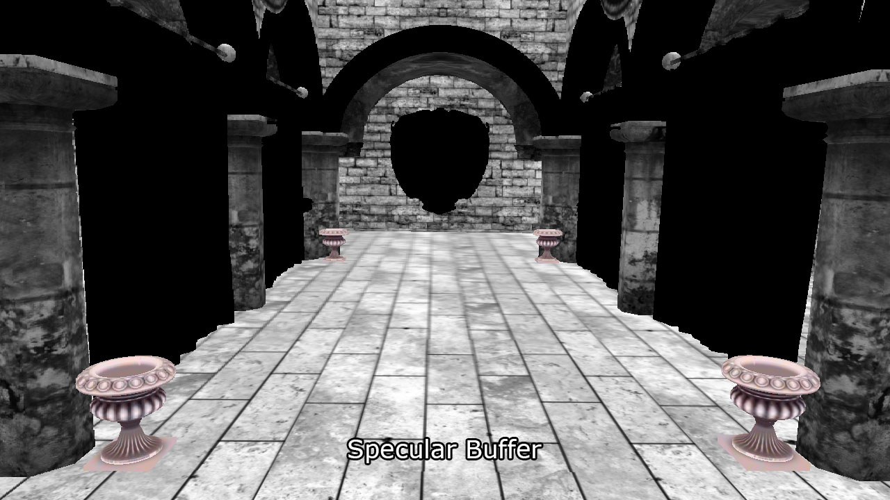
Specular Buffer 镜面缓冲区
与光累积和漫反射缓冲区类似,镜面反射颜色缓冲区使用 R8G8B8A8_UNORM 格式存储为 32 位 4 分量无符号归一化纹理。红色、绿色和蓝色通道用于存储镜面反射颜色,而 Alpha 通道用于存储镜面反射强度。镜面反射强度值通常以 (1…256]或更高范围表示,但需要将其打包到要存储在纹理中的范围 [0…1],要将镜面反射强度打包到纹理中,我使用所描述的方法。在 Michiel van der Leeuw 发表的题为“Deferred Rendering in Killzone 2”的演讲中,他使用以下公式来计算镜面反射强度值:
此函数允许打包 [1…1448.15],范围内的镜面反射功率值,并为正常镜面反射中的值提供良好的精度范围 (1…256),下图显示了打包镜面反射值的趋势。
And the result of the specular buffer after the G-buffer pass looks like this.
G-buffer pass后镜面缓冲区的结果看起来像这样。
Normal Buffer 法线缓冲区
视图空间法线存储在一个 128 位 4 分量浮点缓冲区中,使用 R32G32B32A32_FLOAT 纹理格式。这样大小的法线缓冲区实际上并不是必需的,我可能可以将法线的 X 和 Y 分量打包到一个 32 位 2 分量半精度浮点缓冲区中,并在光照pass中重新计算 z 分量。对于这个实验,我更看重精度和简单性,而不是效率,因为我的 GPU 不受纹理内存的限制,我使用了具有最高精度的最大可能缓冲区。
值得研究其他法线缓冲区的纹理格式,并分析质量与性能之间的权衡。我的假设是,对于法线缓冲区使用较小的纹理格式(例如 R16G16_FLOAT)可能会产生类似质量的结果,同时提供改进的性能。
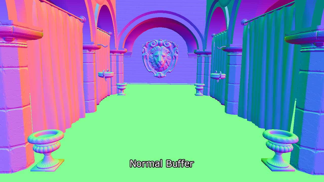
正常缓冲区在 G-Buffer传递后的结果。
上面的图像显示了 G-buffer pass后的正常缓冲区的结果。
Layout Summary 布局摘要
整个 G-buffer 布局看起来与下面显示的表格类似。
| R | G | B | A | |
|---|---|---|---|---|
| Depth/Stencil 深度/模板 | D24_UNORM | S8_UINT | ||
| Light Accumulation 光积累 | R8_UNORM | G8_UNORM | B8_UNORM | A8_UNORM |
| Diffuse | R8_UNORM | G8_UNORM | B8_UNORM | A8_UNORM |
| Specular | R8_UNORM | G8_UNORM | B8_UNORM | A8_UNORM |
| Normal | R32_FLOAT | G32_FLOAT | B32_FLOAT | A32_FLOAT |
Pixel Shader 像素着色器
G-buffer pass的像素着色器与前向渲染器的像素着色器非常相似。主要区别在于 G-buffer pass中不执行任何光照计算。在前向渲染方式中收集材质属性的过程与之前相同,因此我不会在此重复着色器代码的这一部分。
将 G-Buffer数据输出到纹理,每个 G-Buffer纹理将绑定到一个渲染目标输出,使用 PixelShaderOutput 结构。
1 | struct PixelShaderOutput |
由于深度/模板缓冲区绑定到输出合并阶段,因此我们不需要从像素着色器输出深度值。
现在让我们在像素着色器中填充 G 缓冲纹理。
1 | [earlydepthstencil] |
一旦检索到所有材质属性,我们只需要将属性保存到适当的渲染目标中。为简洁起见,读取所有材质属性的源代码已被省略。您可以在本文末尾下载源代码以查看完整的像素着色器。
有了 G-Buffer填充,我们可以在光pass中计算最终的着色。在接下来的部分,我将描述 Guerrilla 在 Killzone 2 中使用的方法,还将描述我使用的实现并解释为什么我使用了不同的方法。
Lighting Pass (Guerrilla)
在这个实验中我使用的延迟着色方式的光照pass的主要灵感来源于 Michiel van der Leeuw 在 2007 年 8 月在加利福尼亚州帕洛阿尔托索尼计算机娱乐图形研讨会上的演示“Killzone 2 中的延迟渲染”[13]。在 Michiel 的演示中,他将光照pass描述为四个阶段:
- Clear stencil buffer to 0,
将模板缓冲区清除为 0, - Mark pixels in front of the far light boundary,
标记在远光边界前面的像素, - Count number of lit pixels inside the light volume,
计算光体内部照亮的像素数量, - Shade the lit pixels
遮住亮起的像素
我将简要描述最后三个步骤。然后,我将介绍我选择用来实现延迟着色方式的光照pass的方法,并解释为什么我选择了与 Michiel 演示中所解释的方法不同的方法。
Determine Lit Pixels 确定照亮的像素
根据 Michiel 的演示,要确定哪些像素被照亮,首先需要渲染光体的背面,并标记在远光边界前面的像素。然后计算在光体前面的像素数量。最后,着色标记的像素并在光体前面的像素后面。
Mark Pixels 标记像素
在第一阶段,将标记在光体后面的像素标记在模板缓冲区中。为此,必须首先将模板缓冲区清零,然后使用以下设置配置管线状态:
- Bind only the vertex shader (no pixel shader is required)
仅绑定顶点着色器(不需要像素着色器) - Bind only the depth/stencil buffer to the output merger stage (since no pixel shader is bound, there is no need for a color buffer)
仅将深度/模板缓冲区绑定到输出合并阶段(因为未绑定像素着色器,所以不需要颜色缓冲区) - Rasterizer State: 光栅化器状态:
- Set cull mode to FRONT to render only the back faces of the light volume
将剔除模式设置为 FRONT 以仅渲染光体的背面
- Set cull mode to FRONT to render only the back faces of the light volume
- Depth/Stencil State: 深度/模板状态
- Enable depth testing 启用深度测试
- Disable depth writes 禁用深度写入
- Set the depth function to GREATER_EQUAL
将深度函数设置为 GREATER_EQUAL - Enable stencil operations
启用模板操作 - Set stencil reference to 1
将模板参考值设置为 1 - Set stencil function to ALWAYS
将模板函数设置为始终 - Set stencil operation to REPLACE on depth pass.
在深度pass上将模板操作设置为替换。
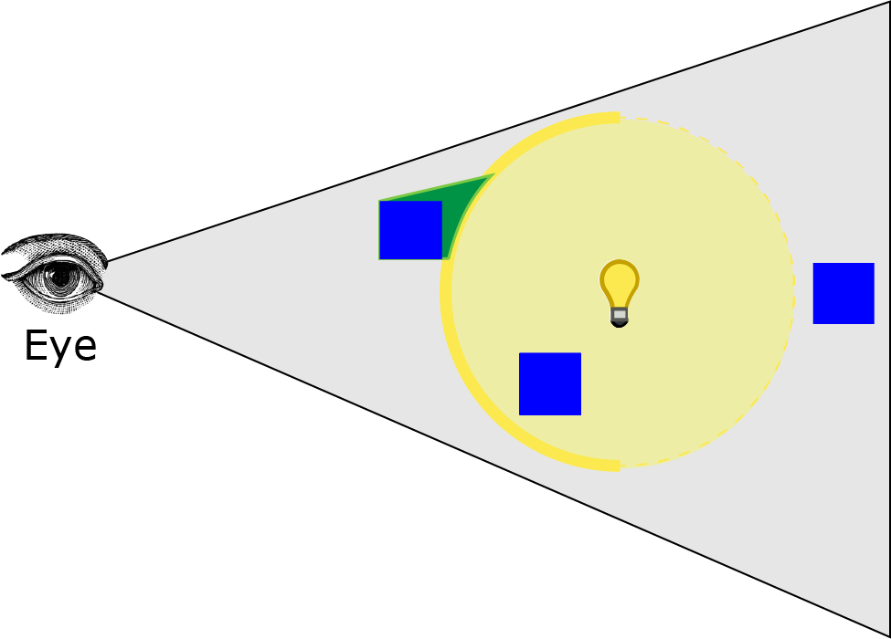
And render the light volume. The image below shows the effect of this operation.
并渲染光体积。下面的图像显示了此操作的效果。
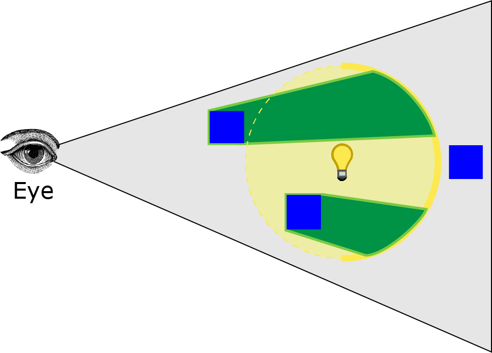
光体的虚线被剔除,只渲染背面的多边形。绿色的体积显示模板缓冲区将被标记为模板参考值的位置。下一步是计算光体内的像素数量。
Count Pixels 计算像素
下一阶段是计算在前一阶段标记的像素数量以及位于光体内部的像素数量。这是通过渲染光体的正面并计算在前一阶段被标记的像素数量以及位于光体正面后面的像素数量来完成的。在这种情况下,管线状态应配置为:
- Bind only the vertex shader (no pixel shader is required)
仅绑定顶点着色器(不需要像素着色器) - Bind only the depth/stencil buffer to the output merger stage (since no pixel shader is bound, there is no need for a color buffer)
仅将深度/模板缓冲区绑定到输出合并阶段(因为未绑定像素着色器,所以不需要颜色缓冲区) - Configure the Rasterizer State:
配置光栅化器状态:- Set cull mode to BACK to render only the front faces of the light volume
将剔除模式设置为后向以仅渲染光体的前面
- Set cull mode to BACK to render only the front faces of the light volume
- Depth/Stencil State: 深度/模板状态
- Enable depth testing 启用深度测试
- Disable depth writes 禁用深度写入
- Set the depth function to LESS_EQUAL
将深度函数设置为 LESS_EQUAL - Enable stencil operations
启用模板操作 - Set stencil reference to 1
将模板参考值设置为 1 - Set stencil operations to KEEP (don’t modify the stencil buffer)
将模板操作设置为 KEEP(不修改模板缓冲区) - Set stencil function to EQUAL
将模板函数设置为 EQUAL
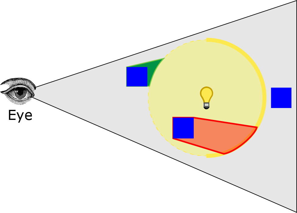
通过遮挡像素查询再次渲染光体积,以计算通过深度和模板操作的像素数量。下图显示了此操作的效果。
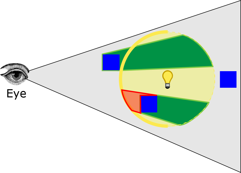
图像中的红色体积显示了在此阶段将被计入的像素。
如果光栅化的像素数量低于一定阈值,则可以跳过着色步骤。如果光栅化的像素数量高于一定阈值,则需要对像素进行着色。
Michiel 的演示中描述的一个步骤,但在这个实验中被跳过的是生成光影地图。像素查询的主要目的是跳过阴影地图的生成。由于在这个实验中我没有进行阴影贴图,所以我完全跳过了自己实现中的这一步骤(稍后将会展示)。
Shade Pixels 阴影像素
根据 Michiel 的方法,最后一步是对位于光体内的像素进行着色。为此,管线状态的配置应与计算像素阶段的管线配置相同,同时启用附加混合,绑定像素着色器,并将颜色缓冲附加到输出合并器阶段。
-
Bind both vertex and pixel shaders
绑定顶点和像素着色器 -
Bind depth/stencil and light accumulation buffer to the output merger stage
将深度/模板和光积累缓冲区绑定到输出合并阶段 -
Configure the Rasterizer State:
配置光栅化器状态:- Set cull mode to BACK to render only the front faces of the light volume
将剔除模式设置为后向以仅渲染光体的前面
- Set cull mode to BACK to render only the front faces of the light volume
-
Depth/Stencil State: 深度/模板状态
- Enable depth testing 启用深度测试
- Disable depth writes 禁用深度写入
- Set the depth function to LESS_EQUAL
将深度函数设置为 LESS_EQUAL - Enable stencil operations
启用模板操作 - Set stencil reference to 1
将模板参考值设置为 1 - Set stencil operations to KEEP (don’t modify the stencil buffer)
将模板操作设置为 KEEP(不修改模板缓冲区) - Set stencil function to EQUAL
将模板函数设置为 EQUAL
-
Blend State: 混合状态:
-
Enable blend operations 启用混合操作
-
Set source factor to ONE
将源因子设置为 ONE -
Set destination factor to ONE
将目的地因子设置为 ONE -
Set blend operation to ADD
将混合操作设置为 ADD
The result should be that only the pixels that are contained within the light volume are shaded.
结果应该是只有包含在光体内的像素才会被着色。
Lighting Pass (My Implementation)
光照pass(我的实现)
Michiel 演示中描述的光照pass存在的问题是,像素查询操作几乎肯定会导致停顿,因为 CPU 必须等待 GPU 查询结果返回。如果使用前一帧(或前 2 帧)的查询结果而不是依赖于当前帧的查询结果,可以避免停顿,这依赖于时间相干理论[15]。这将需要为每个光源创建多个查询对象,因为如果查询对象必须在多个帧之间持久存在,则无法重用查询对象。
由于我在我的实现中没有进行阴影贴图,因此没有明显需要执行 Michiel 演示中描述的像素遮挡查询,从而避免了由查询操作产生的潜在停顿。
Michiel 演示中描述的方法的另一个问题是,如果眼睛在光体内部,则在计算像素和着色像素阶段不会计算或着色任何像素。
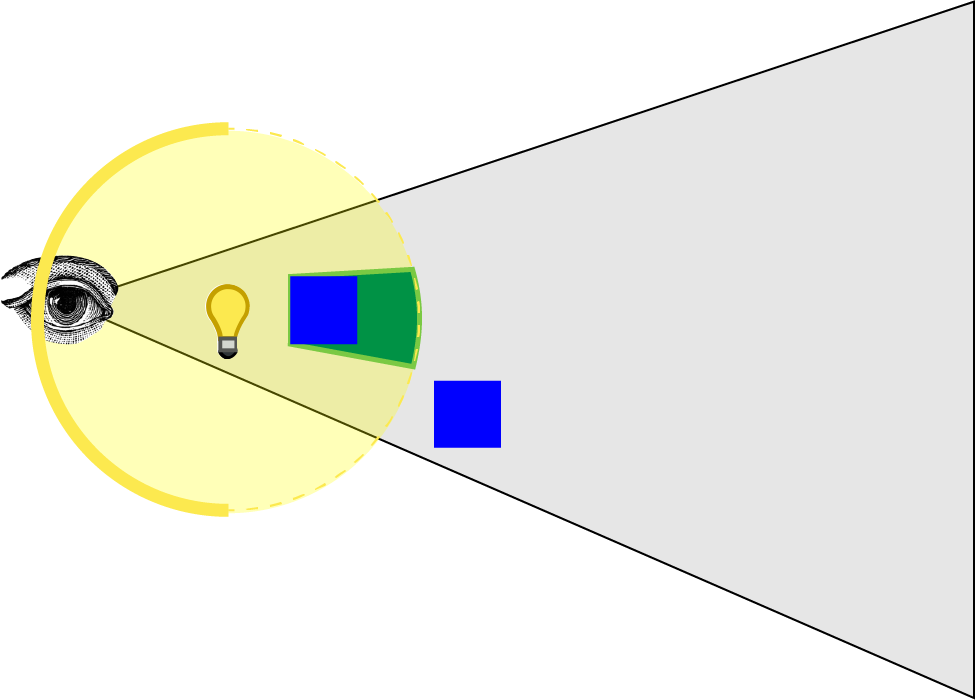
图像中显示的绿色体积代表在第一阶段标记在模板缓冲区中的像素。没有显示红色体积,因为光体的前表面被视锥体剪裁。我尝试通过禁用深度剪裁来解决这个问题,但这只能防止在观察者前面剪裁像素(眼睛后面的像素仍然被剪裁)。
To solve this problem, I reversed Michiel’s method:
为了解决这个问题,我颠倒了米歇尔的方法:
- Clear stencil buffer to 1,
清除模板缓冲区为 1, - Unmark pixels in front of the near light boundary,
取消标记靠近光边界前面的像素, - Shade pixels that are in front of the far light boundary
着色在远光边界前面的像素
我将解释我的实现的最后两个步骤,并描述用于着色像素的方法。
Unmark Pixels 取消标记像素
在我的实现的第一阶段中,我们需要取消标记所有位于光的几何体积前面的像素。这确保了遮挡光体积的像素不会在下一阶段渲染。首先清除模板缓冲区以将所有像素标记为 1,并取消标记位于光体积前面的像素。管线状态的配置如下:
- Bind only the vertex shader (no pixel shader is required)
仅绑定顶点着色器(不需要像素着色器) - Bind only the depth/stencil buffer to the output merger stage (since no pixel shader is bound, there is no need for a color buffer)
仅将深度/模板缓冲区绑定到输出合并阶段(因为未绑定像素着色器,所以不需要颜色缓冲区) - Rasterizer State: 光栅化器状态:
- Set cull mode to BACK to render only the front faces of the light volume
将剔除模式设置为后向以仅渲染光体的前面
- Set cull mode to BACK to render only the front faces of the light volume
- Depth/Stencil State: 深度/模板状态
- Enable depth testing 启用深度测试
- Disable depth writes 禁用深度写入
- Set the depth function to GREATER
将深度函数设置为 GREATER - Enable stencil operations
启用模板操作 - Set stencil function to ALWAYS
将模板函数设置为始终 - Set stencil operation to DECR_SAT on depth pass.
在深度pass上将模板操作设置为 DECR_SAT。
And render the light volume. The image below shows the result of this operation.
然后渲染光体积。下面的图像显示了此操作的结果。
将模板操作设置为 DECR_SAT 将在深度测试通过时将模板缓冲区中的值递减并夹紧到 0。绿色体积显示了模板缓冲区将被递减到 0 的位置。因此,如果眼睛在光体积内部,所有像素仍将在模板缓冲区中标记,因为光体积的前表面将被视锥体剪裁,没有像素将被取消标记。
在下一阶段,将对光体背面前的像素进行着色。
Shade Pixels 阴影像素
在这个阶段,那些既在光体后面的像素前面,又在上一帧中没有标记的像素将被着色。在这种情况下,管线状态的配置将如下所示:
-
Bind both vertex and pixel shaders
绑定顶点和像素着色器 -
Bind depth/stencil and light accumulation buffer to the output merger stage
将深度/模板和光积累缓冲区绑定到输出合并阶段 -
Configure the Rasterizer State:
配置光栅化器状态:- Set cull mode to FRONT to render only the back faces of the light volume
将剔除模式设置为 FRONT 以仅渲染光体的背面 - Disable depth clipping 禁用深度裁剪
- Set cull mode to FRONT to render only the back faces of the light volume
-
Depth/Stencil State: 深度/模板状态
- Enable depth testing 启用深度测试
- Disable depth writes 禁用深度写入
- Set the depth function to GREATER_EQUAL
将深度函数设置为 GREATER_EQUAL - Enable stencil operations
启用模板操作 - Set stencil reference to 1
将模板参考值设置为 1 - Set stencil operations to KEEP (don’t modify the stencil buffer)
将模板操作设置为 KEEP(不修改模板缓冲区) - Set stencil function to EQUAL
将模板函数设置为 EQUAL
-
Blend State: 混合状态:
-
Enable blend operations 启用混合操作
-
Set source factor to ONE
将源因子设置为 ONE -
Set destination factor to ONE
将目的地因子设置为 ONE -
Set blend operation to ADD
将混合操作设置为 ADD
您可能已经注意到,我还在光栅化器状态中禁用了深度裁剪。这样做可以确保如果光体的任何部分超出了远裁剪平面,它不会被裁剪。
The image below shows the result of this operation.
下面的图像显示了此操作的结果。
红色体积显示了在这个阶段将被着色的像素。即使观察者在光体内部,此实现也将正确着色像素。在第二阶段,只有那些在光体后面的背面前面且在前一阶段未标记的像素将被着色。
接下来,我将描述用于实现延迟光照pass的像素着色器。
Pixel Shader 像素着色器
像素着色器仅在上面描述的着色像素阶段期间绑定。它将从 G-Buffer中提取纹理数据,并使用它来使用在前向渲染部分中描述的相同光照模型对像素进行着色。
由于我们所有的光照计算都是在视图空间中执行的,因此我们需要计算当前像素的视图空间位置。
我们将使用屏幕空间位置和深度缓冲区中的值来计算当前像素的视图空间位置。为此,我们将使用 ClipToView 函数将裁剪空间坐标转换为视图空间,并使用 ScreenToView 函数将屏幕坐标转换为视图空间。
为了方便这些功能,我们需要知道屏幕尺寸和摄像机的逆投影矩阵,这些信息应该从应用程序传递给着色器的常量缓冲区中。
1 | // Parameters required to convert screen space coordinates to view space. |
将屏幕空间坐标转换为裁剪空间,我们需要将屏幕空间坐标缩放和平移到裁剪空间,然后通过将裁剪空间坐标乘以投影矩阵的逆矩阵来将裁剪空间坐标转换为视图空间。
1 | // Convert clip space coordinates to view space |
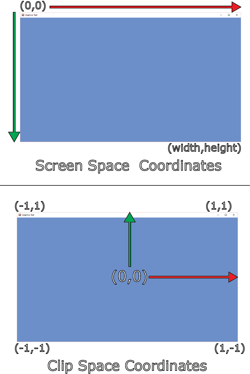
首先,我们需要通过屏幕尺寸来归一化屏幕坐标。这将把以范围([0…屏幕宽度], [0…屏幕高度])表示的屏幕坐标转换为范围([0…1], [0…1])。
在 DirectX 中,屏幕原点(0,0)位于屏幕的左上角,屏幕的 y 坐标从上到下递增。这与裁剪空间中的 y 坐标方向相反,因此我们需要翻转归一化屏幕空间中的 y 坐标,使其在范围内([0…1],[1…0])。然后,我们需要将归一化屏幕坐标缩放 2 倍,使其在范围内([0…2],[2…0]),并将其移位-1,使其在范围内([-1…1],[1…-1])。
现在我们有了当前像素的剪辑空间位置,我们可以使用 ClipToView 函数将其转换为视图空间。这是通过将剪辑空间坐标乘以相机投影矩阵的逆(第 195 行)并除以 w 分量来完成的,以消除透视投影(第 197 行)。
现在让我们在着色器中使用这个函数。
1 | [earlydepthstencil] |
延迟光照像素着色器的输入结构与顶点着色器的输出相同,包括绑定到 SV_Position 系统值语义的位置参数。在像素着色器中使用时,绑定到 SV_Position 语义的参数的值将是当前正在渲染的像素的屏幕空间位置。我们可以使用这个值和深度缓冲区中的值来计算视图空间位置。
由于 G 缓冲纹理与屏幕具有相同的尺寸,因此我们可以使用 Texture2D.Load [16]方法从每个 G 缓冲纹理中提取纹素。Texture2D.Load 方法的纹理坐标是一个 int3,其中 x 和 y 分量是非规范化屏幕坐标中的 U 和 V 纹理坐标,z 分量是要采样的 mipmap 级别。在采样 G 缓冲纹理时,我们总是希望采样 mipmap 级别 0(最详细的 mipmap 级别)。从较低的 mipmap 级别采样会导致纹理显示为块状。如果没有为 G 缓冲纹理生成 mipmaps,则从较低的 mipmap 级别采样将返回黑色纹素。Texture2D.Load 方法在采样纹理时不执行任何纹理过滤,因此在使用线性过滤时比 Texture2D.Sample 方法更快。
一旦我们有屏幕空间位置和深度值,我们就可以使用 ScreenToView 函数将屏幕空间位置转换为视图空间。
在计算光照之前,我们需要从 G 缓冲纹理中采样其他组件。
1 | // View vector |
在第 179 行,从镜面颜色的 alpha pass中解压出镜面率,使用与在 G 缓冲pass中的镜面纹理中打包它所使用的操作的逆操作。
为了检索正确的光属性,我们需要知道光缓冲区中当前光的索引。为此,我们将在常量缓冲区中传递当前光的光索引。
1 | cbuffer LightIndexBuffer : register( b4 ) |
从光列表中检索光属性并计算最终的阴影。
1 | Light light = Lights[LightIndex]; |
您可能会注意到,我们不需要像在正向渲染着色器中那样检查光是否已启用。如果光未启用,则应用程序不应渲染光体积。
我们也不需要检查光是否在当前像素的范围内,因为像素着色器不应该在超出光范围的像素上调用。
光照函数已经在前向渲染部分进行了解释,所以这里不会再进行解释。
在第 203 行,漫反射和镜面项被合并并从着色器中返回。环境光和自发光项已经在光累积缓冲区中的 G 缓冲着色器中计算过了。启用了加法混合后,所有光照项将被正确求和以计算最终的阴影。
在最后一步,我们需要渲染透明物体。
Transparent Pass 透明pass
透明pass用于延迟着色方式与启用了 alpha 混合的前向渲染方式相同。这里没有新信息可提供。我们将在稍后描述的结果部分反思透明pass的性能。
现在让我们来看看本文将解释的最终方式; Forward+。
Forward+
Forward+提升了常规的前向渲染,首先确定哪些光源在屏幕空间中重叠。在着色阶段,只有潜在重叠当前片元的光源需要考虑。我使用“潜在”一词,因为用于确定重叠光源的方式并不完全准确,稍后我会解释。
Forward+ 方式主要包括以下三个pass:
- Light culling 光照剔除
- Opaque pass 不透明pass
- Transparent pass 透明pass
在光照剔除过程中,场景中的每个光源都被排序到屏幕空间的瓦片中。
在不透明pass中,从光剔除pass生成的光列表用于计算不透明几何体的光照。在这个pass中,不需要考虑所有的灯光进行光照,只需要考虑之前被排序到当前片元屏幕空间瓦片中的灯光在计算光照时需要考虑。
透明pass类似于不透明pass,只是用于计算光照的光列表略有不同。我将在接下来的部分中解释不透明pass和透明pass的光列表之间的区别。
Grid Frustums 网格视锥体
在进行光照剔除之前,我们需要计算用于将光源剔除到屏幕空间瓦片中的剔除视锥体。由于剔除视锥体是以视图空间表示的,因此只有在网格的尺寸发生变化(例如,屏幕调整大小)或瓦片的尺寸发生变化时,才需要重新计算。我将解释瓦片的视锥体平面是如何定义的。
屏幕被分成许多方形瓦片。我将所有屏幕瓦片称为光栅。我们需要为每个瓦片指定一个大小。该大小定义了单个瓦片的垂直和水平尺寸。瓦片大小不应该随意选择,而应该选择一个可以由 DirectX 计算着色器中的单个线程组计算的大小。线程组中的线程数应该是 64 的倍数(以利用现代 GPU 上可用的双 warp 调度程序),并且不能超过每个线程组的 1024 个线程。线程组的维度的可能候选者是:
- 8×8 (64 threads per thread group)
8×8(每个线程组 64 个线程) - 16×16 (256 threads per thread group)
16×16(每个线程组 256 个线程) - 32×32 (1024 threads per thread group)
32×32(每个线程组 1024 个线程)
目前,让我们假设线程组的维度为 16×16 个线程。在这种情况下,我们光栅的每个瓦片都有 16×16 个屏幕像素的尺寸。
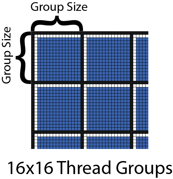
上面的图像显示了一个 16×16 线程组的部分网格。每个线程组由粗黑线分隔,线程组内的线程由细黑线分隔。用于光线剔除的瓦片也以相同的方式分隔。
如果我们以斜角观察瓦片,我们可以可视化需要计算的剔除视锥体。
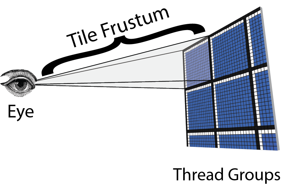
上图显示相机位置(眼睛)是截锥体的原点,瓦片的角点表示截锥体的角点。有了这些信息,我们可以计算出瓦片截锥体的平面。
视锥由六个平面组成,但为了执行光剔除,我们希望预先计算视锥的四个侧面平面。近和远视锥平面的计算将推迟到光剔除阶段。
计算左、右、上和下视锥体平面,我们将使用以下算法:
- Compute the four corner points of the current tile in screen space.
计算屏幕空间中当前瓦片的四个角点。 - Transform the screen space corner points to the far clipping plane in view space.
将屏幕空间的角点转换到视图空间中的远裁剪平面。 - Build the frustum planes from the eye position and two other corner points.
从眼睛位置和另外两个角点构建视锥平面。 - Store the computed frustum in a RWStructuredBuffer.
将计算得到的视锥存储在 RWStructuredBuffer 中。
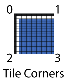
如果我们知道位于平面上的三个点,那么可以计算出一个平面[18]。如果我们给瓦片的角点编号,如上图所示,我们可以使用视图空间中的眼睛位置和其他两个角点来计算视锥体平面。
例如,我们可以使用以下点来计算视锥体平面,假设顺时针顺序:
- Left Plane: Eye, Bottom-Left (2), Top-Left (0)
左平面:眼睛,左下角(2),左上角(0) - Right Plane: Eye, Top-Right (1), Bottom-Right (3)
右平面:眼睛,右上角(1),右下角(3) - Top Plane: Eye, Top-Left (0), Top-Right (1)
顶部平面:眼睛,左上角(0),右上角(1) - Bottom Plane: Eye, Bottom-Right (3), Bottom-Left (2)
底部平面:眼睛,右下角(3),左下角(2)
如果我们知道了位于一个平面上的三个点,就可以知道这个平面的发现
如果n已被归一化,那么给出一个位于平面上方的点P,可以与法线点乘得出P到平面的距离(看不懂这里的可以去复习下从深度图重建片元世界空间坐标的内容)
这被称为平面的常法线形式[18],也可以表示为
Where n==(a,b,c) and X=(x,y,z) given that X is a point that lies in the plane.
In the HLSL shader, we can define a plane as a unit normal n and the distance to the origin d.
1 | struct Plane |
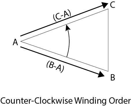
给定三个不共线的逆时针排列在平面上的点,我们可以使用 HLSL 中的 ComputePlane 函数计算平面。
1 | // Compute a plane from 3 noncollinear points that form a triangle. |
一个截头锥体被定义为由四个平面构成的结构。
1 | // Compute a plane from 3 noncollinear points that form a triangle. |
为了预先计算网格视锥体,我们需要为网格中的每个瓦片调用一个计算着色器核心。例如,如果屏幕分辨率为 1280×720,光栅被划分为 16×16 个瓦片,我们需要计算 80×45(3,600)个视锥体。如果一个线程组包含 16×16(256)个线程,我们需要派发 5×2.8125 个线程组来计算所有的视锥体。当然,我们不能派发部分线程组,所以在派发计算着色器时,我们需要将其四舍五入到最接近的整数。在这种情况下,我们将派发 5×3(15)个线程组,每个线程组包含 16×16(256)个线程,在计算着色器中,我们必须确保简单地忽略超出屏幕边界的线程。
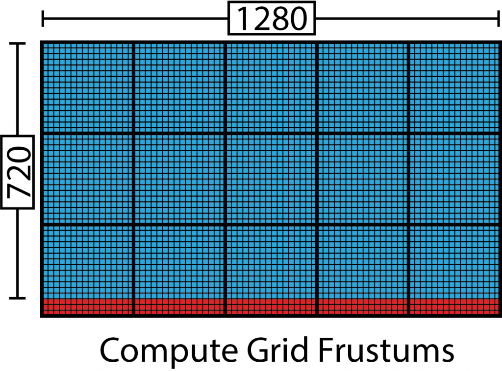
上面的图像显示了将被调用以生成瓦片视锥的线程组,假设一个 16×16 线程组。粗黑线表示线程组边界,细黑线代表线程组中的线程。蓝色线程代表将用于计算瓦片视锥的线程,红色线程应该简单地跳过视锥瓦片计算,因为它们超出了屏幕的大小。
我们可以使用以下公式来确定派遣的维度:
有了这些信息,我们可以调度用于预计算网格视锥的计算着色器。
Grid Frustums Compute Shader 网格截锥体计算着色器
默认情况下,计算着色器的线程组大小将为 16×16 个线程,但应用程序可以在着色器编译期间定义不同的块大小。
1 |
我们将定义一个通用结构来存储常见的计算着色器输入变量。
1 | struct ComputeShaderInput |
See [10] for a list of the system value semantics that are available as inputs to a compute shader.
参见[10],列出可用作计算着色器输入的系统值语义。
除了 HLSL 提供的系统值之外,我们还需要知道当前调度中线程的总数和线程组的总数。不幸的是,HLSL 没有为这些属性提供系统值语义。我们将把所需的值存储在一个名为 DispatchParams 的常量缓冲区中。
1 | // Global variables |
numThreads 变量的值可用于确保调度中的线程不会超出屏幕范围,如前所述。
为了存储计算的网格视锥体的结果,我们还需要创建一个足够大的结构化缓冲区,以存储每个瓦片的一个视锥体。这个缓冲区将绑定到 out_Frustrum RWStructuredBuffer 变量,使用统一访问视图。
1 | // View space frustums for the grid cells. |
Tile Corners in Screen Space 屏幕空间中的瓦片角点
在计算着色器中,我们首先需要做的是使用调度中当前线程的全局 ID 确定瓦片视锥体角点的屏幕空间点。
1 | // A kernel to compute frustums for the grid |
将全局线程 ID 转换为屏幕空间位置,我们只需乘以光栅中一个瓦片的大小。屏幕空间位置的 z 分量为-1,因为我使用的是右手坐标系,在视图空间中相机朝向-z 轴。如果您使用左手坐标系,应该将 z 分量设为 1。这样我们就得到了远裁剪平面上瓦片角点的屏幕空间位置。
Tile Corners in View Space 在视图空间中的Tile角
接下来,我们需要使用关于延迟渲染像素着色器部分中描述的 ScreenToView 函数,将屏幕空间位置转换为视图空间。
1 | float3 viewSpace[4]; |
Compute Frustum Planes 计算视锥体平面
利用瓦片角的视图空间位置,我们可以构建视锥体平面。
1 | // Now build the frustum planes from the view space points |
Store Grid Frustums 存储网格视锥体
最后,我们需要将截头锥体写入全局内存。我们必须小心,不要访问超出分配的截头锥体缓冲区边界的数组元素。
1 | // Store the computed frustum in global memory (if our thread ID is in bounds of the grid). |
现在我们有预先计算的网格视锥体,我们可以在光遮挡计算着色器中使用它们。
Light Culling 光照剔除
在 Forward+渲染方式的下一步中,使用在前一节中计算的网格视锥体来剔除光源。只需要在应用程序开始时计算一次网格视锥体,或者在屏幕尺寸或瓦片大小发生变化时重新计算。但是,光源剔除阶段必须在每一帧中发生,即摄像机移动、光源位置移动或场景中的对象发生变化影响深度缓冲区内容时。这些事件中的任何一个都可能发生,因此通常每一帧都执行光源剔除是安全的。
The basic algorithm for performing light culling is as follows:
执行光源剔除的基本算法如下:
- Compute the min and max depth values in view space for the tile
计算视图空间中瓦片的最小和最大深度值 - Cull the lights and record the lights into a light index list
剔除灯光并将灯光记录到灯光索引列表中 - Copy the light index list into global memory
将灯光索引列表复制到全局内存中
Compute Min/Max Depth Values 计算最小/最大深度值
算法的第一步是计算光栅每个瓦片的最小和最大深度值。最小和最大深度值将用于计算我们剔除视锥体的近平面和远平面。
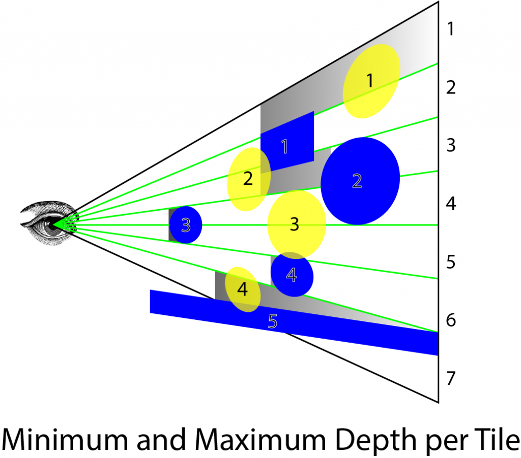
上面的图像显示了一个示例场景。蓝色物体代表场景中的不透明物体。黄色物体代表光源,阴影灰色区域代表从每个瓦片的最小和最大深度值计算出的瓦片视锥体。绿色线条代表光栅的瓦片边界。从上到下,瓦片编号为 1-7,不透明物体编号为 1-5,灯光编号为 1-4。
第一个瓦片的最大深度值为 1(在投影剪辑空间中),因为有一些像素未被不透明几何体覆盖。在这种情况下,裁剪视锥体非常大,可能包含不影响几何体的灯光。例如,灯光 1 包含在瓦片 1 内,但灯光 1 不影响任何几何体。在几何边界处,裁剪视锥体可能非常大,可能包含不影响任何几何体的灯光。
在瓦片 2 中,最小和最大深度值相同,因为物体 2 直接面向摄像机并填充整个瓦片。当我们执行光体积的实际裁剪时,这不会成为问题。
物体 3 完全遮挡了光 3,因此在着色任何片元时将不予考虑。
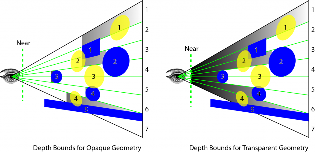
上述图像显示了不透明几何体每个瓦片的最小和最大深度值。对于透明几何体,我们只能裁剪在最大深度平面后面的光体积,但必须考虑所有在所有不透明几何体前面的光源。原因是在执行深度预处理步骤以生成用于确定每个瓦片的最小和最大深度的深度纹理时,我们不能将透明几何体渲染到深度缓冲区中。如果这样做,那么我们将无法正确照亮位于透明几何体后面的不透明几何体。这个问题的解决方案在一篇名为“平铺式前向着色”的文章中有所描述,作者是 Markus Billeter、Ola Olsson 和 Ulf Assarsson。在光照剔除计算着色器中,将生成两个光列表。第一个光列表仅包含影响不透明几何体的光源。第二个光列表仅包含可能影响透明几何体的光源。在对不透明几何体执行最终着色时,我将发送第一个列表,而在渲染透明几何体时,我将发送第二个列表到片元着色器。
在讨论光剔除计算着色器之前,我将讨论在计算着色器中用于构建光列表的方法。
Light List Data Structure 光列表数据结构
用于存储每个瓦片光列表的数据结构在 Ola Olsson 和 Ulf Assarsson 的论文“平铺着色”中有描述。Ola 和 Ulf 描述了一个分为两部分的数据结构。第一部分是光栅,它是一个存储光索引列表中值的偏移量和计数的二维网格。这种方式类似于索引缓冲区,它引用顶点缓冲区中的顶点索引。
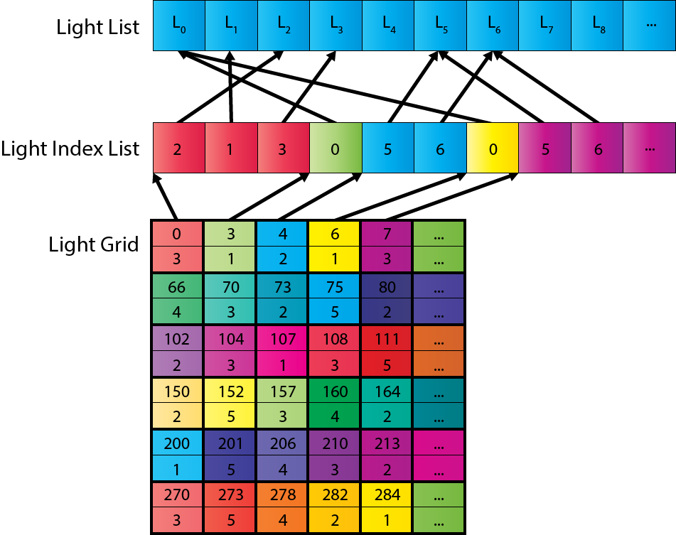
光栅的大小基于用于光剔除的屏幕瓦片数量。光索引列表的大小基于每个瓦片预期的平均重叠光数。例如,对于分辨率为 1280×720 且瓦片大小为 16×16 的屏幕,结果是 80×45(3,600)的光栅。假设每个瓦片平均有 200 个光,这将需要一个包含 720,000 个索引的光索引列表。每个光索引占用 4 个字节(对于 32 位无符号整数),因此光列表将消耗 2.88 MB 的 GPU 内存。由于我们需要为透明和不透明几何体分别列出列表,这将总共消耗 5.76 MB。尽管 200 个光可能是对每个瓦片平均重叠光数的过高估计,但存储使用并不过分。
生成光栅和光索引列表,首先在计算着色器中生成一个组共享的光索引列表。使用全局光索引列表计数器来跟踪当前索引进入全局光索引列表。全局光索引计数器是原子地递增的,以便没有两个线程组可以使用全局光索引列表中的相同范围。一旦线程组在全局光索引列表中“保留”了空间,组共享的光索引列表就会被复制到全局光索引列表中。
The following pseudo code demonstrates this technique.
以下伪代码演示了这种方式。
1 | function CullLights( L, C, G, I ) |
在前三行中,将网格中当前瓦片的索引定义为 t。本地光索引列表定义为 i,用于对当前瓦片执行光剔除的瓦片视锥体定义为 f。
第 4、5 和 6 行循环遍历全局光列表,并根据当前切片的裁剪视锥体对光源进行裁剪。如果光源在视锥体内,则将光源索引添加到本地光源索引列表中。
在第 7 行,全局光源索引列表中的当前索引会增加本地光源索引列表中包含的光源数量。在增加之前,全局光源索引列表计数器的原始值会存储在本地计数器变量 c 中。
在第 8 行,光栅 G 会使用当前切片的偏移量和计数值更新全局光源索引列表。
最后,在第 9 行,将本地光索引列表复制到全局光索引列表中。
然后,在片元着色器中使用光栅和全局光索引列表执行最终着色。
Frustum Culling 视锥体裁剪
对光体执行截锥体裁剪,将呈现两种截锥体裁剪方法:
- Frustum-Sphere culling for point lights
点光源的截锥-球体裁剪 - Frustum-Cone culling for spot lights
聚光灯锥体裁剪
球体的裁剪算法相对简单。锥体的裁剪算法稍微复杂一些。首先我会描述视锥-球体算法,然后我会描述锥体裁剪算法。
Frustum-Sphere Culling 视锥-球体裁剪
我们已经在前一节中看到了修剪视锥的定义,标题为计算网格视锥。一个球被定义为视图空间中的一个中心点和一个半径。
1 | struct Sphere |
如果一个球完全包含在平面的负半空间中,则认为球在平面“内部”。如果一个球完全包含在任何视锥平面的“内部”,则它在视锥之外。
我们可以使用以下公式来确定球体与平面之间的有符号距离[18]:
l是从球体到平面距离,c是球体中心点,n是平面法线,d是从平面到视点距离
如果l小于-r(为球体半径),那么我们可以认为球体被平面的一半完整包裹
1 | // Check to see if a sphere is fully behind (inside the negative halfspace of) a plane. |
然后我们可以迭代应用 SphereInsidePlane 函数来确定球体是否包含在裁剪视锥体内部。
1 | // Check to see of a light is partially contained within the frustum. |
由于球是在视图空间中描述的,我们可以根据其 z 位置和到近和远裁剪平面的距离快速确定是否应该根据其 z 位置和到近和远裁剪平面的距离来剔除光线。如果球要么完全在近裁剪平面的前面,要么完全在远裁剪平面的后面,那么光线可以被丢弃。否则,我们必须检查光线是否在剔除视锥体的范围内。
SphereInsideFrustum 假定一个右手坐标系,摄像机朝向负 z 轴。在这种情况下,远平面逼近负无穷大,因此我们必须检查球体是否更远(在负方向上小于)。对于左手坐标系,应该在第 268 行交换 zNear 和 zFar 变量。
Frustum-Cone Culling 锥体截锥体裁剪
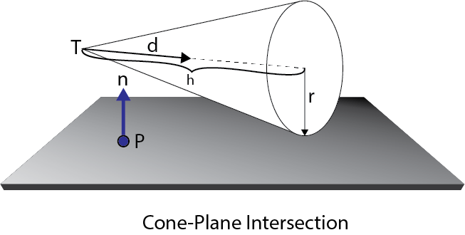
为了执行截锥体剔除,我将使用 Christer Ericson 在其名为“实时碰撞检测”的书中描述的技术 [18]。圆锥体可以通过其尖端 T、归一化方向向量 d、圆锥体高度 h 和底面半径 r 来定义
在 HLSL 中,锥台被定义为
1 | struct Cone |
要测试一个圆锥体是否完全包含在平面的负半空间中,只需要测试两个点。
- The tip T of the cone
- The point Q that is on the base of the cone that is farthest away from the plane in the direction of n
If both of these points are contained in the negative half-space of any of the frustum planes, then the cone can be culled.
如果这两点都包含在任何锥台平面的负半空间中,则可以剔除锥体。
为了确定在 n 方向上距离平面最远的点 Q,我们将计算一个平行但相反的中间向量 m到 n 并垂直于 d
Q是通过从尖端 T沿锥轴 d 步进距离 h获得的,然后沿圆锥体的底面距平面 −m 的正半空间的距离为 r倍。
如果 n×d为零,则锥轴 d 平行于平面法线 n 和 m 将是零向量。这种特殊情况不需要专门处理,因为在这种情况下,方程简化为:
导致需要测试的正确点。
计算出 T 和 Q 后,我们可以测试这两个点是否位于平面的负半空间中。如果是的话,我们就可以得出结论,光线可以被剔除。为了测试一个点是否在平面的负半空间中,我们可以使用以下方程:
其中l 是点到平面的有符号距离,X 是要测试的点。如果 l 为负,则该点包含在平面的负半空间中。
在 HLSL 中,函数 PointInsidePlane 用于测试一个点是否在平面的负半空间内。
1 | // Check to see if a point is fully behind (inside the negative halfspace of) a plane. |
而 ConeInsidePlane 函数用于测试锥体是否完全包含在平面的负半空间中。
1 | // Check to see if a cone if fully behind (inside the negative halfspace of) a plane. |
ConeInsideFrustum 函数用于测试锥体是否包含在裁剪截锥内。如果锥体在截锥内部,则此函数将返回 true;如果锥体完全包含在任何裁剪平面的负半空间中,则返回 false。
1 | bool ConeInsideFrustum( Cone cone, Frustum frustum, float zNear, float zFar ) |
首先,我们检查圆锥体是否被近裁剪平面或远裁剪平面剪裁。否则,我们必须检查视锥体的四个平面。如果圆锥体在任何裁剪平面的负半空间中,该函数将返回 false。
现在我们可以将这些组合起来定义光照剔除计算着色器。
Light Culling Compute Shader 光照剔除计算着色器
光照剔除计算着色器的目的是更新片元着色器所需的全局光索引列表和光栅格。每帧需要更新两个列表:
- Light index list for opaque geometry
不透明几何的光索引列表 - Light index list for transparent geometry
透明几何的光索引列表
为了区分 HLSL 计算着色器中的这两个列表,我将使用前缀“o_”来指代不透明列表,“t_”来指代透明列表。这两个列表将在光剔除计算着色器中更新。
首先,我们将声明光照剔除计算着色器所需的资源。
1 | // The depth from the screen space texture. |
为了读取深度预pass生成的深度值,结果深度纹理需要被发送到光照剔除计算着色器。DepthTextureVS 纹理包含深度预pass的结果。
in_Frustums 是在计算 frustums 计算着色器中计算并在标题为 Grid Frustums Compute Shader 的部分中描述的结构化缓冲区。
我们还需要跟踪全局光索引列表中的索引。
1 | // Global counter for current index into the light index list. |
o_LightIndexCounter 是不透明几何体全局光索引列表的当前索引,t_LightIndexCounter 是透明几何体全局光索引列表的当前索引。
尽管光指数计数器是 RWStructuredBuffer 类型,但这些缓冲区仅在索引 0 处包含单个无符号整数。
1 | // Light index lists and light grids. |
光索引列表存储为一维无符号整数数组,但光栅存储为二维纹理,其中每个“纹素”是一个二分量无符号整数向量。光栅纹理使用 R32G32_UINT 格式创建。
为了存储每个瓦片的最小和最大深度值,我们需要声明一些组共享变量来存储最小和最大深度值。原子递增函数将被用来确保只有一个线程组中的线程可以更改最小/最大深度值,但不幸的是,着色器模型 5.0 不提供用于浮点值的原子函数。为了规避这个限制,深度值将被存储为无符号整数在组共享内存中,这将被原子地比较和更新每个线程。
1 | groupshared uint uMinDepth; |
由于用于执行裁剪的视锥体将是组中所有线程的相同视锥体,因此保留组中所有线程的视锥体的副本是有意义的。只有组中的线程 0 需要从全局内存缓冲区复制视锥体,我们还减少了每个线程所需的本地寄存器内存量。
1 | groupshared Frustum GroupFrustum; |
我们还需要声明组共享变量来创建临时光列表。我们将需要一个用于不透明和透明几何体的单独列表。
1 | // Opaque geometry light lists. |
LightCount 将跟踪与当前瓷砖视锥相交的灯光数量。
LightIndexStartOffset 是全局光索引列表中的偏移量。此索引将被写入光栅,并在将本地光索引列表复制到全局光索引列表时用作起始偏移量。
本地光指数列表将允许我们在单个瓦片中存储多达 1024 个灯光。这个最大值几乎永远不会达到(至少不应该!)。请记住,当我们为全局光列表分配存储空间时,我们考虑了每个瓦片平均 200 个灯光。有可能有一些瓦片包含超过 200 个灯光(只要不超过 1024 个),也有一些瓦片包含少于 200 个灯光,但我们预计平均每个瓦片约有 200 个灯光。如前所述,每个瓦片平均 200 个灯光的估计可能是一个过高的估计,但由于 GPU 内存对于这个项目并不是一个限制性约束,我可以在估计上保守一些。
更新本地光计数器和光列表,我将定义一个名为 AppendLight 的辅助函数。不幸的是,我还没有弄清楚如何将组共享变量作为参数传递给函数,所以现在我将定义同一函数的两个版本。函数的一个版本用于更新不透明几何体的光索引列表,另一个版本用于透明几何体。
1 | // Add the light to the visible light list for opaque geometry. |
如果您正在阅读此内容,并且知道如何将组共享变量作为参数传递给 HSLS 中的函数,请在下方评论中留下您的解决方案。(请不要猜测。在建议之前确保您的解决方案有效)。
InterlockedAdd 函数确保组共享的灯计数变量一次只能由一个线程更新。这样我们就避免了多个线程同时尝试增加组共享的灯计数时可能发生的竞争条件。
在递增之前存储在索引本地变量中的光计数值,用于更新组共享光索引列表中的光索引。
计算每个瓦片的最小和最大深度范围的方法取自于 2011 年 Johan Andersson 的演示文稿“战地 3 中的 DirectX 11 渲染” [3] 和 Ola Olsson 与 Ulf Assarsson 的“平铺着色” [5]。
在光剔除计算着色器中,我们将首先读取当前线程的深度值。线程组中的每个线程将仅为当前线程采样深度缓冲区一次,因此组中的所有线程将为单个瓦片采样所有深度值。
1 | // Implementation of light culling compute shader is based on the presentation |
由于我们只能对整数执行原子操作,在第 100 行,我们将浮点深度的位重新解释为无符号整数。由于我们期望深度图中的所有深度值都存储在范围[0…1]内(即所有正深度值),因此将浮点数重新解释为整数仍然允许我们正确地对这些值执行比较。只要我们不尝试对无符号整数深度值执行任何算术运算,我们应该能够获得正确的最小值和最大值。
1 | if ( IN.groupIndex == 0 ) // Avoid contention by other threads in the group. |
由于我们正在设置组共享变量,组中只需要一个线程来设置它们。实际上,如果我们不将这些变量的写入限制在组中的单个线程上,HLSL 编译器将生成竞争条件错误。
为了确保组中的每个线程在计算着色器中达到相同的点,我们调用 GroupMemoryBarrierWithGroupSync 函数。这确保了对组共享内存的任何写操作已经完成,并且组中所有线程的线程执行都已经达到了这一点。
接下来,我们将确定当前瓦片的最小和最大深度值。
1 | InterlockedMin( uMinDepth, uDepth ); |
InterlockedMin 和 InterlockedMax 方法用于根据当前线程深度值原子更新 uMinDepth 和 uMaxDepth 组共享变量。
我们再次需要使用 GroupMemoryBarrierWithGroupSync 函数,以确保所有对组共享内存的写操作都已提交,并且组中的所有线程都已到达计算着色器中的此点。
在找到当前瓦片的最小和最大深度值之后,我们可以将无符号整数重新解释为浮点数,以便我们可以使用它来计算当前瓦片的视空间裁剪平面。
1 | float fMinDepth = asfloat( uMinDepth ); |
在第 118 行,最小和最大深度值作为无符号整数需要重新解释为浮点值,以便可以用来计算视图空间中的正确点。
视图空间深度值是使用 ScreenToView 函数计算的,并提取视图空间中位置的 z 分量。我们只需要这些值来计算视图空间中的近裁剪面和远裁剪面,因此我们只需要知道与观察者的距离。
在为透明几何体剔除光源时,我们不希望使用深度图中的最小深度值。相反,我们将使用摄像机的近裁剪面来裁剪光源。在这种情况下,我们将使用 nearClipVS 值,即到摄像机近裁剪面的距离。
由于我使用右手坐标系,相机指向视图空间中的负 z 轴,因此最小深度裁剪平面是使用指向负 z 方向的法线 n 计算的轴,到原点 d 的距离为 -minDepth。我们可以通过使用平面的常量正规形式来验证这是正确的:
通过代入n=(0,0,-1), X=(x,y,z),
这意味着 (0,0,zmin) 是裁剪平面上的最小深度点。
1 | // Cull lights |
如果线程组中的每个线程同时检查全局灯光列表中的一个灯光,那么我们可以在第 132 行定义的 for 循环的每次迭代中检查 16×16 (256) 个灯光。循环以 i=groupIndex 开始对于循环的每次迭代, i = groupIndex 以及 i 递增, BLOCK_SIZE×BLOCK_SIZE BLOCK_SIZE × BLOCK_SIZE 。这意味着对于 BLOCK_SIZE=16 BLOCK_SIZE = 16 ,线程组中的每个线程将检查每 256 个灯,直到检查完所有灯为止。
- Thread 0 checks: { 0, 256, 512, 768, … }
线程 0 检查:{ 0, 256, 512, 768, … } - Thread 1 checks: { 1, 257, 513, 769, … }
线程 1 检查:{1, 257, 513, 769, …} - Thread 2 checks: { 2, 258, 514, 770, … }
线程 2 检查:{2, 258, 514, 770, …} - …
- Thread 255 checks: { 255, 511, 767, 1023, … }
线程 255 检查:{255, 511, 767, 1023, …}
For 10,000 lights, the for loop only needs 40 iterations (per thread) to check all lights for a tile.
对于 10,000 个灯光,for 循环只需要 40 次迭代(每个线程)来检查一个瓦片上的所有灯光。
First we’ll check point lights using the SphereInsideFrustum function that was defined earlier.
首先,我们将使用之前定义的 SphereInsideFrustum 函数来检查点光源。
1 | switch ( light.Type ) |
在第 142 行,使用光的位置和范围定义了一个球体。
首先,我们检查光是否在瓦片视锥体内,使用摄像机的近裁剪平面和从深度缓冲区读取的最大深度。如果光体积在这个范围内,它将被添加到透明几何体的光索引列表中。
要检查光是否应该被添加到不透明几何体的全局光索引列表中,我们只需要检查之前在第 128 行定义的最小深度裁剪平面。如果光在透明几何体的裁剪视锥体内并且在最小深度裁剪平面的前面,则将光的索引添加到不透明几何体的光索引列表中。
接下来,我们将检查聚光灯。
1 | case SPOT_LIGHT: |
检查圆锥体几乎与检查球体相同,因此我在这里不会详细介绍。聚光锥体底部的半径未与光一起存储,因此需要为 ConeInsideFrustum 函数计算。要计算圆锥体底部的半径,我们可以使用聚光角的正切乘以圆锥体的高度。
最后,我们需要检查方向灯。这绝对是这个功能中最容易的部分。
1 | case DIRECTIONAL_LIGHT: |
没有可靠的方法来筛选定向光源,因此如果我们遇到定向光源,我们别无选择,只能将其索引添加到光源索引列表中。
确保线程组中的所有线程都已将其光线记录到组共享的光线索引列表中,我们将调用 GroupMemoryBarrierWithGroupSync 函数来同步组中的所有线程。
在将所有未被剔除的光线添加到组共享的光线索引列表之后,我们需要将其复制到全局光线索引列表中。首先,我们将更新全局光线索引列表计数器。
1 | // Update global memory with visible light buffer. |
我们将再次使用 InterlockedAdd 函数,将全局光线索引列表计数器增加已追加到组共享光线索引列表中的光线数量。在第 194 行和 198 行,光栅将使用全局光线索引列表的偏移量和光线计数进行更新。
为了避免竞态条件,只有线程组中的第一个线程将用于更新全局内存。
在第 201 行,必须再次同步线程组中的所有线程,然后我们才能更新全局光索引列表。
1 | // Update global memory with visible light buffer. |
更新不透明和透明的全局光索引列表,我们将允许所有线程使用类似于之前在 132-183 行上显示的迭代光列表的方法,将单个索引写入光索引列表。
在这一点上,光栅和全局光索引列表都包含了供像素着色器使用的必要数据,以执行最终着色。
Final Shading 最终着色
Forward+渲染方式的最后部分是最终着色。这种方法与在标题为前向渲染-像素着色器的部分讨论的标准前向渲染方式没有什么不同,只是我们不再通过整个全局光列表进行循环,而是使用在光剔除阶段生成的光索引列表。
除了在标准前向渲染部分中描述的属性之外,Forward+像素着色器还需要获取在光照剔除阶段生成的光索引列表和光网格。
1 | StructuredBuffer<uint> LightIndexList : register( t9 ); |
在渲染不透明几何体时,必须注意为不透明几何体绑定光索引列表和光网格;在渲染透明几何体时,为透明几何体绑定光索引列表和光网格。当然,这似乎是显而易见的,但最终着色像素着色器的唯一区别因素是绑定到像素着色器阶段的光索引列表和光网格。
1 | [earlydepthstencil] |
大部分像素着色器的代码与前向渲染像素着色器的代码相同,因此为简洁起见在此省略。主要概念显示在第 298 行,其中从屏幕空间位置计算出光栅格中的瓦片索引。使用瓦片索引,从光栅格中在第 301 行和 302 行读取起始偏移和光计数。
在定义在第 306 行的 for 循环中,循环遍历光计数并从光索引列表中读取光的索引,然后使用该索引从全局光列表中检索光。
Now let’s see how the performance of the various methods compare.
现在让我们看看各种方法的性能如何比较。
Experiment Setup and Performance Results 实验设置和性能结果
为了衡量各种渲染方式的性能,我在 NVIDIA GeForce GTX 680 GPU 上使用了 Crytek Sponza 场景[11],屏幕分辨率为 1280×720。摄像机靠近世界原点,灯光被动画化以围绕世界原点旋转。
我使用两种场景测试了每种渲染方式:
- Large lights with a range of 35-40 units
具有 35-40 个单位范围的大灯 - Small lights with a range of 1-2 units
1-2 个单位范围内的小灯光
在场景中放置几个(2-3 个)大灯是一个现实的情景(例如主光、补光和背光[25])。这些灯光可能是投射阴影的灯光,用来营造氛围。在屏幕上放置许多(超过 5 个)大灯并不一定是一个现实的情景,但我想看看在使用大面积、填充屏幕的灯光时各种方式是如何扩展的。
在游戏中使用许多小灯光是一个更为现实的情景。许多小灯光可以用来模拟区域光或反射光效果,类似于全局光照算法的效果,通常只能通过光照图或光探针来模拟,如“前向渲染”部分所述。
尽管演示支持定向光,但我没有测试使用定向光进行渲染的性能。定向光是大面积填充屏幕的灯光,类似于具有 35-40 单位范围的灯光(第一个情景)。
在这两种情况下,灯光是随机放置在场景的边界内的。 Sponza 场景被缩小,使其边界在 X 轴和 Z 轴上约为 30 个单位,在 Y 轴上约为 15 个单位。
每个图表显示一组曲线,代表渲染方式的各个阶段。曲线的横轴代表场景中灯光的数量,纵轴代表以毫秒为单位的运行时间。每个图表还显示了最小和最大阈值。最小阈值显示为图表中的绿色水平线,代表理想帧率为每秒 60 帧(FPS)或 16.6 毫秒。最大阈值显示为图表中的红色水平线,代表最低可接受的帧率为每秒 30 帧(FPS)或 33.3 毫秒。
Forward Rendering Performance 前向渲染性能
让我们首先分析使用大灯光的前向渲染方式的性能。
Large Lights 大灯
下面的图表显示了使用大灯光的前向渲染方式的性能结果。
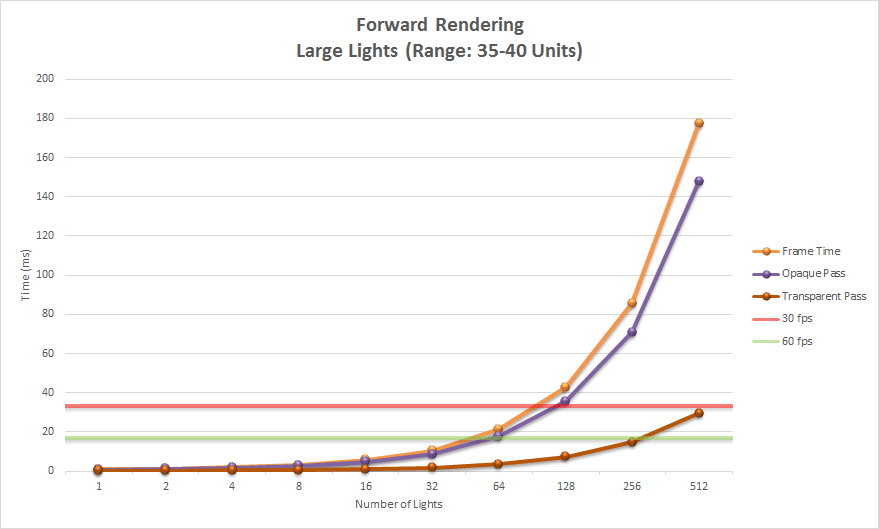
该图显示了前向渲染方式的两个主要阶段。紫色曲线显示了不透明pass,深红色曲线显示了透明pass。橙色线显示了渲染场景的总时间。
如图所示,渲染不透明几何体需要最长的时间,并且随着灯光数量的增加呈指数增长。渲染透明几何体的时间也呈指数增长,但场景中的透明几何体要比不透明几何体少得多,因此增长看起来更为渐进。
即使使用非常大的灯光,标准前向渲染可以渲染 64 个动态灯光,同时保持帧速率低于 30 FPS 的最大阈值。超过 512 个灯光后,帧时间变得无法测量。
由此我们可以得出结论,如果场景中包含超过 64 个大型可见光源,您可能需要考虑使用不同于前向渲染的渲染方式。
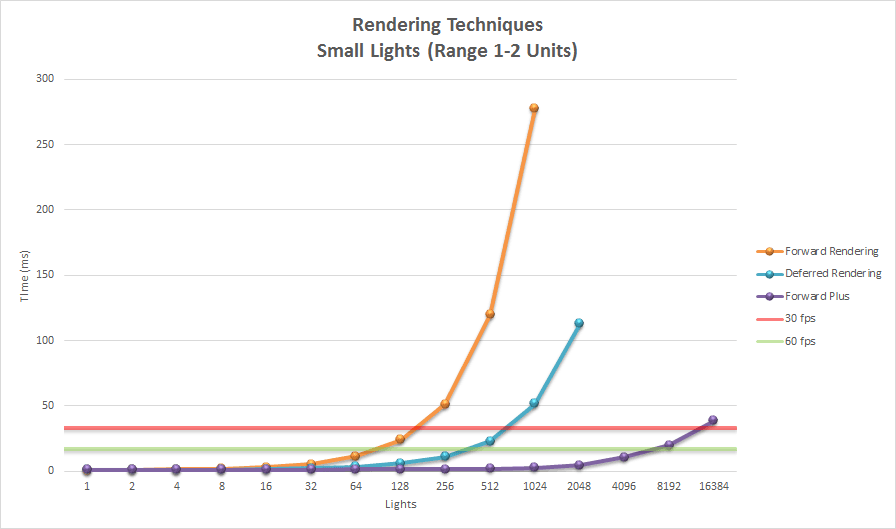
Small Lights 小灯
正向渲染在场景包含许多小灯时表现更好。在这种情况下,渲染方式可以处理两倍多的灯光,同时仍保持可接受的性能。超过 1024 个灯光后,帧时间变得如此之高,不再值得测量。
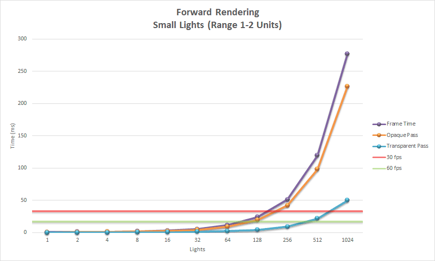
我们再次看到,大部分时间都花在渲染不透明几何体上,这并不令人意外。大灯和小灯的趋势相似,但使用小灯时,我们可以创建两倍多的灯光,同时实现可接受的帧速率。
接下来我将分析延迟渲染方式的性能。
Deferred Rendering Performance 延迟渲染性能
同样的实验被重复进行,但这次使用了延迟渲染方式。让我们首先分析使用大屏幕填充灯光的性能。
Large Lights 大灯
下面的图表显示了使用大灯光的延迟渲染的性能结果。
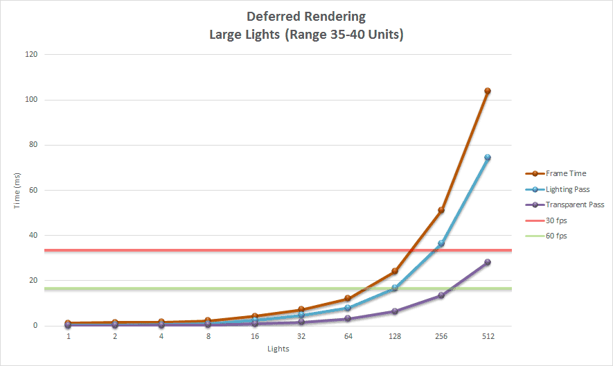
使用延迟渲染渲染大型灯光,与前向渲染相比,效果仅略有改善。由于渲染透明几何体使用与前向渲染方式完全相同的代码路径,因此使用前向渲染与延迟渲染渲染透明几何体的性能几乎相同。如预期的那样,在渲染透明几何体时没有性能优势。
使用延迟渲染渲染不透明几何体的边际性能优势主要是由于前向渲染在遮挡几何体上执行的冗余光照计算数量减少。使用深度预pass可以减轻前向渲染时执行的冗余光照计算,从而允许在执行昂贵的光照计算之前拒绝片元。延迟渲染隐式受益于早期 z 测试和前向渲染期间未执行的模板操作。
Small Lights 小灯
下面的图表显示了使用小灯光进行延迟渲染的性能结果。
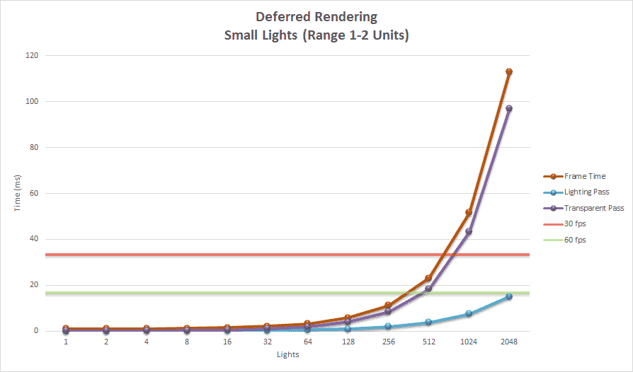
图表显示,延迟渲染能够渲染 512 个小型动态光源,同时仍保持可接受的帧率。在这种情况下,渲染透明几何体的时间远远超过了渲染不透明几何体的时间。如果只渲染不透明对象,那么延迟渲染方式能够渲染 2048 个光源,同时保持在低于最低可接受的 60 FPS 阈值以下的帧率。渲染透明几何体在大约 700 个光源后远远超过了最大阈值。
Forward Plus Performance Forward+性能
同样的实验再次使用平铺的前向渲染进行了重复。首先,我们将分析使用大光源的性能特征。
Large Lights 大灯
下面的图表显示了使用大场景灯光的平铺前向渲染的性能结果。
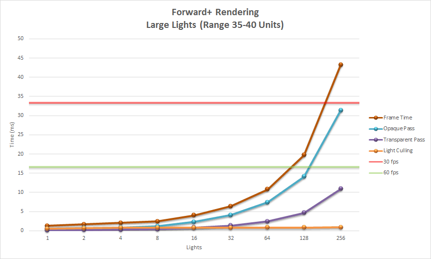
图表显示,瓷砖式前向渲染不适合渲染具有许多大光源的场景。在场景中渲染 512 个铺满屏幕的光源会导致问题,因为演示仅考虑每个瓷砖平均有 200 个光源。使用 512 个大光源,超过了 200 个光源的平均值,许多瓷砖简单地变黑。
使用大光源,光源剔除阶段从未超过 1 毫秒,但不透明pass和透明pass很快超过了最大帧速率阈值 30 FPS。
Small Lights 小灯
该图表显示了使用小光源的瓷砖式前向渲染的性能。
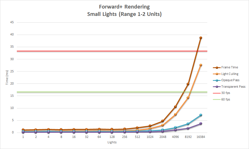
前向加真正在使用许多小灯光时发挥作用。在这种情况下,我们看到光剔除阶段(橙线)是渲染方式的主要瓶颈。即使有超过 16,000 个灯光,渲染不透明(蓝线)和透明(紫线)几何体都低于实现所需帧速率 60 FPS 的最低阈值。大部分帧时间被光剔除阶段消耗。
现在让我们看看这三种方式如何相互比较。
Techniques Compared 方式比较
首先,我们将看看这三种方式在使用大灯时如何相互比较。
Large Lights 大灯
下面的图表显示了使用大灯光时三种渲染方式的性能。
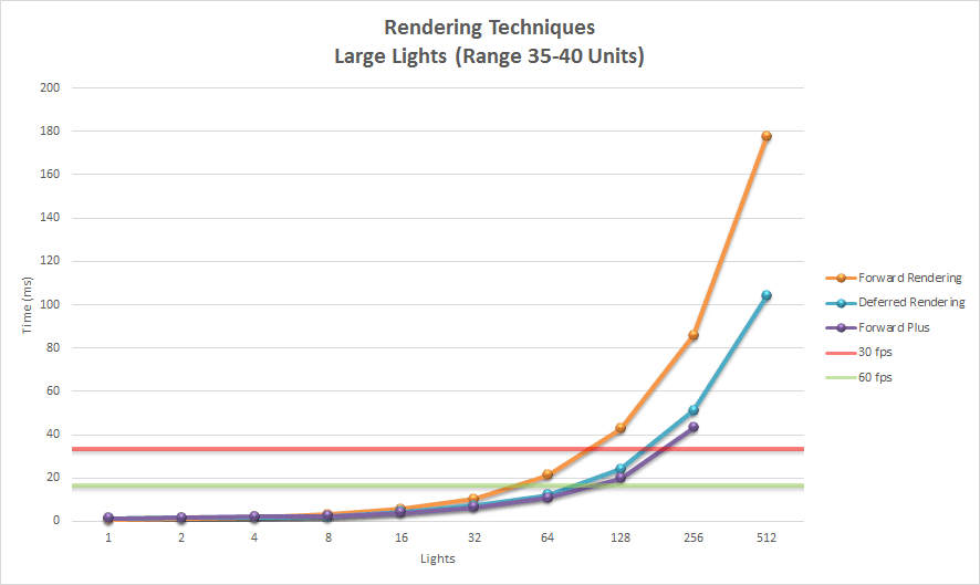
正如预期的那样,在渲染大光源时,前向渲染是最昂贵的渲染算法。延迟渲染和瓦片前向渲染在性能上是可比的。即使我们忽略场景中透明几何体的渲染,延迟渲染和瓦片前向渲染具有类似的性能特征。
如果我们只考虑有几个大灯光的场景,前向渲染、延迟渲染或前向加渲染之间仍然没有明显的性能优势。
如果我们考虑执行前向渲染与延迟渲染与平铺前向渲染所需的内存占用,那么传统的前向渲染具有最小的内存使用量。
无论场景中灯光数量如何,延迟渲染每个额外的 G 缓冲渲染目标每像素大约需要四个字节的 GPU 内存。平铺前向渲染需要额外的 GPU 存储用于光索引列表和光栅格,即使场景只包含少量动态光也必须存储。
- Deferred Rendering (Diffuse, Specular, Normal @ 1280×720): +11 MB
延迟渲染(漫反射,镜面反射,法线 @ 1280×720):+11 MB - Tiled Forward Rendering (Light Index List, Light Grid @ 1280×720): +5.76 MB
平铺式前向渲染(光索引列表,1280×720 光栅):+5.76 MB
延迟渲染的额外存储需求基于每像素 32 位(4 字节)的三个全屏缓冲区。深度/模板缓冲区和光积累缓冲区不被视为额外存储,因为标准前向渲染也使用这些缓冲区。
平铺式前向渲染的额外存储需求基于两个光索引列表,每个瓦片平均存储 200 个光源,以及两个 80×45 的光栅,每个格子存储 2 个无符号整数。
如果 GPU 存储在目标平台上是一种稀缺资源,并且场景中不需要太多的光照,传统的前向渲染仍然是最佳选择。
Small Lights 小灯
下面的图表显示了使用小灯光时三种渲染方式的性能。
在小灯光的情况下,瓷砖式前向渲染在渲染时间方面显然是赢家。直到大约 128 个灯光左右,延迟和瓷砖式前向渲染在性能上是可比的,但当场景包含许多动态灯光时,它们很快就会分道扬镳。此外,我们必须考虑到延迟渲染方式的大部分消耗在渲染透明对象上。如果透明对象不是必需的话,那么延迟渲染可能是一个可行的选择。
即使使用小灯光,延迟渲染也需要更多的绘制调用来渲染光体的几何形状。使用延迟渲染,每个光体至少必须渲染两次,第一次绘制调用更新模板缓冲区,第二次绘制调用执行光照方程。如果图形平台对过多的绘制调用非常敏感,那么延迟渲染可能不是最佳选择。
与大灯光场景类似,当场景中只渲染少量灯光时,三种方式的性能特征相似。在这种情况下,我们必须考虑延迟和平铺前向渲染所施加的额外内存需求。同样,如果 GPU 内存稀缺且场景中不需要许多动态灯光,则标准前向渲染可能是一个可行的解决方案。
Future Considerations 未来考虑
在这个项目中工作时,我发现了一些问题,这些问题在未来值得考虑。
- General Issues: 一般问题:
- Size of the light structure
轻结构的大小
- Size of the light structure
- Forward Rendering: 前向渲染
- Depth pre-pass 深度预pass
- View frustum culling of visible lights
查看视锥体裁剪可见光
- Deferred Rendering: 延迟渲染
- Optimize G-buffers 优化 G-Buffer
- Rendering of directional lights
定向光的渲染
- Tiled Forward Rendering 平铺正向渲染
- Improve light culling 改进光剔除
General Considerations 一般考虑
在此演示中使用的每种渲染方式中,只有一个存储定向光、点光和聚光灯的全局光列表,存储在单个数据结构中。为了存储执行正确光照所需的所有属性,每个单独的光结构需要 160 字节的 GPU 内存。如果我们只存储描述光源所需的绝对最小信息,我们可以利用改进的光数据缓存,并可能改善所有渲染方式的渲染性能。这可能需要有额外的数据结构,只存储计算着色器或片元着色器所需的相关信息,或者创建定向光、聚光灯和点光的单独列表,以便不存储与光源无关的冗余信息在数据结构中。
Forward Rendering 前向渲染
此前向渲染方式的实现没有尝试优化前向渲染管线。根据视锥体剔除光源将是改善前向渲染器渲染性能的合理方法。
作为正向渲染方式的第一步,执行深度预先通行将使我们能够利用早期 z 测试来消除冗余的光照计算。
Deferred Rendering 延迟渲染
在创建延迟渲染方式的实现时,我并没有花太多时间评估延迟渲染的性能与所使用的 G-buffer 纹理格式有关。G-buffer 的布局是为了简单和易用而选择的。例如,用于存储视图空间法线的 G-buffer 纹理使用了一个 4 分量 32 位浮点缓冲。将这个渲染目标存储为一个 2 分量 16 位定点缓冲不仅会减少缓冲区大小 75%,还会改善纹理缓存。唯一需要更改的是在着色器中用于打包和解包法线数据的方法。为了将法线打包到 G-buffer 中,我们只需要将法线的归一化 32 位浮点 x 和 y 值转换为 16 位浮点值并存储在渲染目标中。在光照pass中解包法线时,我们可以从缓冲区中读取 16 位分量,并通过以下公式计算法线的 z 分量:
这将导致法线的 z 分量在 [0⋯1] 范围内始终为正。这通常不是问题,因为法线始终存储在视图空间中,并且如果法线的 z 分量为负,则它将是背面的,并且背面的多边形无论如何都应该被剔除。
延迟渲染器的另一个潜在改进领域是处理定向光源。目前的实现将定向光源渲染为全屏四边形在光照pass中。这可能不是最佳方法,因为即使是少量的定向光源也会导致严重的过度绘制,并可能成为填充率受限硬件的问题。为了缓解这个问题,我们可以将定向光源的光照计算移到 G-buffer pass,并将定向光源的光照贡献累积到光积累缓冲区中,类似于环境和发射项的应用方式。
这种方式可以通过在 G-Buffer传递之前执行深度预pass来进一步改进,以允许提前进行 z 测试,以消除多余的光照计算。
使用延迟渲染的一个优点是阴影贴图可以被回收利用,因为在光照pass一次只渲染一个光源,所以只需要分配一个阴影贴图。将定向光的光照计算移动到 G 缓冲pass会要求在 G 缓冲pass之前需要准备好定向光使用的任何阴影贴图。只有在场景中有很多投射阴影的定向光时才会出现问题。如果使用了很多投射阴影的定向光,在 G 缓冲pass中执行定向光的光照计算的方法可能不可行。
Tiled Forward Rendering 平铺式前向渲染
从实验结果可以看出,光剔除阶段需要相当长的时间来执行。如果光剔除阶段的性能得到改进,那么我们就可以获得平铺式前向渲染方式的整体性能提升。也许我们可以执行一个早期剔除步骤,消除不在视锥体内的光源。这将需要创建另一个计算着色器,对场景中的所有光源执行视锥体剔除,但不是对所有光源执行 3,600 个视锥体的剔除,只需要检查视锥体。这样,调度中的每个线程只需要检查一小部分光源是否在视锥体内。在根据较大的视锥体剔除光源之后,每个瓦片的光剔除计算着色器只需要检查包含在视锥体内的光源。
光照剔除阶段的另一个改进可能是使用稀疏八叉树来存储八叉树每个节点的光列表。如果节点中的光数量超过某个最大阈值,就会对节点进行分割。在八叉树中不包含任何光的节点可以从八叉树中移除,并且在最终渲染过程中无需考虑。
DirectX 12 引入了体积平铺资源[20],可用于实现稀疏八叉树。八叉树中没有任何光源的节点不需要任何后备内存。我不确定这将如何实现,但值得调查。
瓷砖化前向渲染方式的另一个改进领域是提高光照剔除的准确性。视锥剔除可能导致将光视为包含在瓷砖中,而实际上光体的任何部分都不包含在瓷砖中。
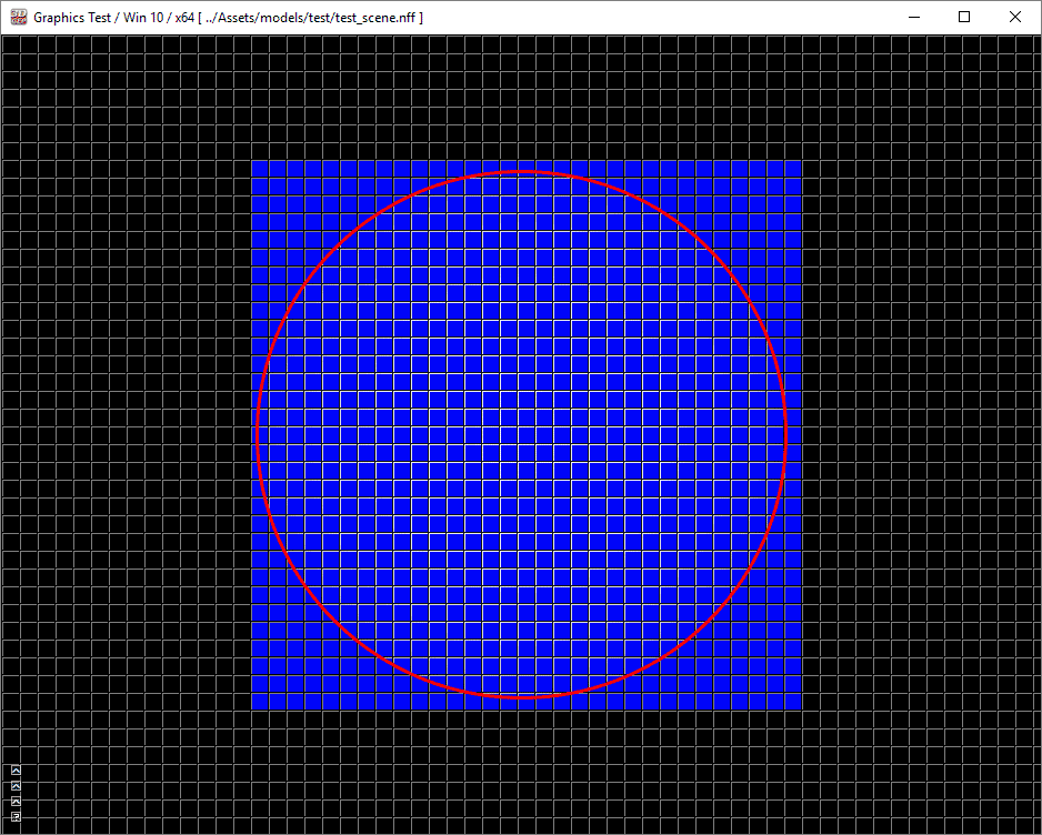
如上图所示,一个点光源用红色圆圈标出。图中的蓝色瓷砖显示了哪些瓷砖检测到圆圈包含在瓷砖的视锥体内。当然,红色圆圈内的瓷砖应该检测到点光源,但是在角落的瓷砖是误报。这是因为球体不能被瓷砖视锥体的任何平面完全拒绝。
如果我们放大到左上角的瓷砖(在上面的视频中用绿色标出),我们可以检查瓷砖的顶部、左侧、底部和右侧截锥面。如果您播放视频,您会看到球部分包含在瓷砖的四个截锥面中,因此光线无法被剔除。
在 2015 年 GDC 由 Gareth Thomas [21]演示的演示中,他提出了几种改进基于瓦片的计算渲染准确性的方法。他建议在光遮挡计算着色器中使用并行归约而不是原子最小/最大函数。他的性能分析显示,通过使用并行归约而不是原子最小/最大,他能够实现 11-14%的性能提升。
为了提高光遮挡的准确性,Gareth 建议使用轴对齐边界框(AABB)来近似瓦片视锥体。使用 AABB 来近似瓦片视锥体的大小被证明是一种成功减少误报数目的方法,而不需要进行昂贵的相交测试。为了执行球体-AABB 相交测试,Gareth 建议使用 James Arvo 在《图形宝石》系列第一版中描述的非常简单的算法。
使用最小/最大深度边界进行基于瓦片的光遮挡时的另一个问题出现在具有大深度不连续性的瓦片中,例如当前景几何体仅部分重叠瓦片时。
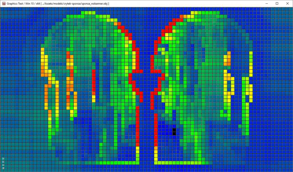
蓝色和绿色瓦片中包含非常少的光。在这种情况下,最小和最大深度值非常接近。红色瓦片表示该瓦片包含许多光,因为深度差异很大。在加雷斯·托马斯的演示中[21],他建议将视锥体分成两半,并为分割后的每半部分计算最小和最大深度值。这意味着光剔除算法必须对每个瓦片执行两倍的工作量,但他的性能分析显示,使用这种方式可以将总帧时间减少约 10-12%。
更有趣的性能优化是一种称为“集群着色”的方法,由 Ola Olsson、Markus Billeter 和 Ulf Assarsson 在他们的论文《集群延迟和前向着色》[23]中提出。他们的方法将具有相似属性(3D 位置和法线)的视图样本分组到集群中。场景中的灯光被分配到集群,并且每个集群的灯光列表在最终着色中使用。在他们的论文中,他们声称能够处理一百万个光源,同时保持实时帧速率。
其他空间划分算法也可能在改进基于瓦片的计算着色器性能方面取得成功。例如,使用二叉空间划分(BSP)树将光源分割到二叉树的叶子节点中。在执行最终着色时,只需要考虑片元存在的 BSP 叶子节点中的光源进行光照。
另一个可能用于减少冗余光照计算的数据结构是稀疏体素八叉树,由 Cyril Crassin 和 Simon Green 在 OpenGL Insights [24]中描述。该数据结构不是用于存储材质信息,而是用于存储每个节点中包含的光源索引列表。在最终着色期间,根据片元的 3D 位置从八叉树中查询光源索引列表。
Conclusion 结论
在本文中,我描述了三种渲染方式的实现:
- Forward Rendering Forward 渲染
- Deferred Rendering 延迟渲染
- Tiled Forward (Forward+) Rendering
平铺前向(Forward+)渲染
我已经表明传统前向渲染非常适合需要支持多种着色模型和半透明对象的场景。前向渲染也非常适合只有少量动态光源的场景。分析表明,包含少于 100 个动态场景光源的场景在商用硬件上仍然表现得相当好。当 GPU 内存稀缺且不需要支持许多动态光源时(例如在移动设备或嵌入式设备上),传统前向渲染可能是最佳选择,因为前向渲染在不需要多个阴影贴图时具有较低的内存占用。
延迟渲染最适合不需要多个着色模型或半透明对象的情况,但需要许多动态场景光源的情况。延迟渲染非常适合许多投射阴影的光源,因为在光照pass中可以在连续光源之间共享单个阴影贴图。延迟渲染不适合 GPU 内存有限的设备。在三种渲染方式中,延迟渲染具有最大的内存占用量,每像素每个 G 缓冲纹理需要额外 4 字节(在分辨率为 1280×720 的屏幕分辨率下每个纹理约为 3.7 MB)。
瓦片前向渲染需要一定的初始开销来调度光照剔除计算着色器,但是具有许多动态光源的瓦片前向渲染的性能很快超过了前向渲染和延迟渲染的性能。瓦片前向渲染需要少量额外的内存。在屏幕分辨率为 1280×720 时,需要大约 5.7 MB 的额外存储空间来存储光索引列表和光栅,使用 16×16 个瓦片。瓦片前向渲染要求目标平台支持计算着色器。如果计算着色器不可用,则可以在 CPU 上执行光照剔除,并将光索引列表和光栅传递给像素着色器,但性能折衷可能会抵消进行光照剔除的好处。
平铺式前向渲染本地支持多材质和半透明材质(使用两个光索引列表),不透明和半透明材质都可以从平铺式前向渲染提供的性能增益中受益。
尽管平铺的前向着色似乎是对生命、宇宙和一切的答案(实际上是 42),但这种方式仍有改进空间。聚类延迟渲染[23]应该能够在增加内存需求的情况下表现得更好。也许通过使用稀疏体纹理[20]可以缓解聚类延迟渲染的内存需求,但这还有待观察。
Download the Demo 下载演示
源代码(包括预构建的可执行文件)可以从 GitHub 使用下面的链接下载。该存储库的大小接近 1GB,并包含所有预构建的第三方库和 Crytek Sponza 场景[11]。
https://github.com/3dgep/ForwardPlus
引用
 微信
微信 支付宝
支付宝